Chapter 3: Mechanical Installation
24 |
P a g e
DOC-S0508-1R14-IMEI02 • Technical Manual • Issue
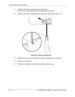
4.
Route photo eye cables up the side guides using pre-attached clips to secure cable from
getting damaged.
5.
Route side opposite cable, through side plate, along horizontal profile, and through other
side plate
It is much easier to route these cables when you are at step 5 of the
3.1.2
Assemble the Door
section of this manual. If attempting this method,
ensure cable does not come free on install and get damaged or pinched.
6.
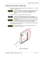
Temporarily leave both excesses of cable by the motor for the electrician/electrical body
to route to control box.
If more than one pair of photo eye is used, do not install two transmitters on
the same side.
Make sure eyes are free of dirt and are properly aligned for proper operation.
3.6. Install covers
Install covers in the manor that they were taken off during the unpacking stage of the install.
Assure all fasteners are installed and tightened. Limit the torque of drills and impacts, as to not to
strip threads on guides or cover fasteners.
Do not attach activations or add-ons to drum cover, fasteners piercing
cover have the potential to damage curtain material.
Do not attach activations or add-ons to counter weight cover, fasteners
piercing cover will disrupt or bind the travel of the counter weight. Damage
will occur to the door.
3.7. Door Limit Position
The door Limits are positions that the door will stop at both in the OPEN and CLOSE position.
The OPEN position should be set so that the last tooth of the retaining zipper is above the
reintroduction point by 1 ½”.
The CLOSE position should be such that the retaining zippers edge is just making contact with
the floor. See Figure 3-16.


