E.T. Systems UMPETHA, Installer'S Instructions
Introducing the E.T. Systems UMPETHA - a revolutionary product designed to simplify your life. To ensure a hassle-free installation, we provide comprehensive Installer's Instructions in a user-friendly manual. Download it for free from our website to unlock the full potential of this innovative technology.
Share
Download


Reviews:
No comments
Related manuals for UMPETHA

BG 3000-B1
Brand: Chamberlain Pages: 45

Pitbull 400
Brand: Accessmatic Pages: 39

K2R E
Brand: Primere Pages: 24

FLOOR 830
Brand: GBD Pages: 28

CM3-DCFP
Brand: Calimet Pages: 24

ELIXO 3S
Brand: SOMFY Pages: 72

BD1522
Brand: Accessmatic Pages: 39

TOO Series
Brand: Nice Pages: 44

SFAB2024
Brand: Nice Pages: 44

LIVI 902
Brand: Dea Pages: 16

NEO QK-N400
Brand: quiko Pages: 2

FA70230E
Brand: CAME Pages: 20

DA461
Brand: Abloy Pages: 32

EZgate
Brand: Gate Tel Pages: 15

KC12
Brand: Coline Pages: 5

SHAFT-30
Brand: DoorHan Pages: 8
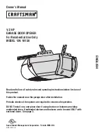
139.10158
Brand: Craftsman Pages: 84

FROG-CD
Brand: CAME Pages: 2


