30
SECTION 5
MAINTENANCE
5.1 GENERAL
The purpose of this section is to provide servicing instructions to the service
technician. The RAY 210 is designed to provide long periods of trouble-free
operation. It is recognized, however, that environmental and other factors may
result in a need for occasional service.
5.1.1 How to contact Raymarine Technical Support
The Americas: +1 800 539-5539 ext.2444 or +1 603 881-5200 ext.2444
UK, Rest of the World: +44 23 6971 4713
Our Technical Support Specialists are available to answer installation, operation,
and trouble-shooting questions about your Raymarine unit Our Technical
Support Department may also be reached via the Internet, where a
comprehensive library of frequently asked questions and solutions is available.
http://www.raymarine.com/support
Accessories and Parts
The Americas: 1-800-539-5539 ext.2333 or (603) 647-7530 ext.2333
UK, Rest of the World: +44 23 9269 3611 ext. 2029,
[email protected]
Many Raymarine accessory items and parts are available through your
authorized Raymarine dealer. However, if you are in need of an item not
available through your retailer feel free to contact our Customer Service
department. If you are uncertain about what item to choose for your Raymarine
unit please contact our Technical Support Department prior to placing your
order.
Product Repair and Service: +1 800 539 5539 ext. 2118
In the unlikely event your Raymarine unit should develop a problem please
contact the Raymarine dealer from where the unit was purchased. Your
Raymarine dealer is best equipped to handle your service needs. Service may
also be obtained by returning your unit to Raymarine's Product Repair Centres at
the addresses below:
The Americas:
Service Department,
Raymarine Inc.,
22 Cotton Road, Unit H
Nashua
NH 03063-4219
UK, Rest of the World:
Service Department,
Raymarine Ltd.,
Anchorage Park
Portsmouth, Hampshire
PO3 5TD
Summary of Contents for RAY 210VHF
Page 2: ......
Page 3: ......
Page 4: ......
Page 6: ......
Page 8: ......
Page 10: ......
Page 12: ......
Page 19: ...7 Figure 2 2 Outline and Mounting Dimensions...
Page 30: ...18 Figure 3 1 Layout of Controls and Connectors...
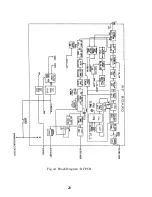
Page 40: ...28 Fig 4 1 Block Diagram RF PCB...
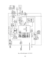
Page 41: ...29 Fig 4 2 Block Diagram CPU PCB...
Page 55: ...43 6 2 RAY210 ASSEMBLY DRAWING...
Page 57: ...45 6 3 SCHEMATIC DIAGRAM Fig 6 1 Schematic diagram RF PCB...
Page 58: ...46 Fig 6 2 Schematic diagram CPU PCB l...
Page 59: ...47 Fig 6 2 Schematic diagram CPU PCB 2...
Page 60: ...48 Fig 6 3 RF PCB Layout Top View...
Page 61: ...49 Fig 6 4 RF PCB Layout Rear View...
Page 62: ...50 Fig 6 5 CPU PCB Layout Top view...
Page 63: ...51 Fig 6 5 CPU PCB Layout Rear View...
Page 64: ...52...
Page 75: ...63...


