


19
23) Microphone Speaker On - Off:
When [FUNC] key and [M5] key are pressed together for more than 10 seconds,
2 beeps sound and the microphone speaker is turned on / off. This setting
remains in memory after power source is cut off.
24) Master Reset:
A master reset is performed when power source is turned on while [FUNC] key
and [16/9] are pressed simultaneously. All channels will be cleared from
memory and the 16 PLUS channel will be automatically programmed back to
channel 16. Two audible beeps will follow completion of the reset.
25) Watching of power source voltage:
When the power source voltage (voltage supplied from the ship) drops below
11.0V, “dcv” is displayed on LCD with 7 segments and “V”. This indication is
continued until power source voltage recovers to 12.0V or more, or until power
source is cut off.
26) Check on antenna condition:
Antenna condition (open / short) is checked while 25 watts TX output power is
transmitted. If any defect is detected, “An” is displayed on the LCD with 7
segments. This indication is continued until the defect of the antenna is
improved, or until power source is cut off.
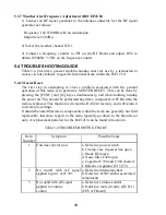
3.2.2 LCD Display
A number of characters appear on the LCD display. The following list describes
the characters and when they will appear.
DESENS: will appear on the LCD display when the radio is in Desensitised
mode.
DW (Dual Watch): will appear on the LCD display when the radio is set to
monitor channel 16 or 9 and a selected channel.
DWX (Dual Watch plus Weather): will appear on the LCD display when the
radio is set to monitor channel 16 or 9, a selected channel, and a weather
channel.
INTL (International): will appear on the LCD display when International
channel frequencies are selected. When the INTL display is extinguished, U.S.
channel frequencies are selected.
Summary of Contents for RAY 210VHF
Page 2: ......
Page 3: ......
Page 4: ......
Page 6: ......
Page 8: ......
Page 10: ......
Page 12: ......
Page 19: ...7 Figure 2 2 Outline and Mounting Dimensions...
Page 30: ...18 Figure 3 1 Layout of Controls and Connectors...
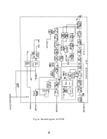
Page 40: ...28 Fig 4 1 Block Diagram RF PCB...
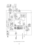
Page 41: ...29 Fig 4 2 Block Diagram CPU PCB...
Page 55: ...43 6 2 RAY210 ASSEMBLY DRAWING...
Page 57: ...45 6 3 SCHEMATIC DIAGRAM Fig 6 1 Schematic diagram RF PCB...
Page 58: ...46 Fig 6 2 Schematic diagram CPU PCB l...
Page 59: ...47 Fig 6 2 Schematic diagram CPU PCB 2...
Page 60: ...48 Fig 6 3 RF PCB Layout Top View...
Page 61: ...49 Fig 6 4 RF PCB Layout Rear View...
Page 62: ...50 Fig 6 5 CPU PCB Layout Top view...
Page 63: ...51 Fig 6 5 CPU PCB Layout Rear View...
Page 64: ...52...
Page 75: ...63...