


17
17) [DIM] (Dimmer) key :
The [DIM] key changes backlighting level for the front panel. The backlighting
is in the off condition when the RAY210 is first turned on. There are four levels
for front panel illumination (high, medium, low, and off), Pressing the [DIM]
key one time turns the backlight to its brightest setting (high). Each subsequent
press of the backlight key decreases the level of illumination. Once the backlight
is decreased to the “off” condition, the next press of the [DIM] key returns the
backlight to high.
18) [VOLT] (voltmeter) key :
Pressing this key will activate the unique digital voltmeter feature for fast
verification of input DC voltage to your RAY210.
To activate the voltmeter, press [VOLT] key. The display will then show the
input DC voltage for five seconds, then will return to previous operation.
19) [D/L] (sensitivity) key :
The receiving sensitivity is changed by pressing this key. When the RAY210 is
turned on, sensitivity is set high. To reduce receiving sensitivity, press [D/L]
key. When at low sensitivity setting "DESENS11 is displayed on the LCD.
Note: When your radio is interfered with by pagers, land mobile and TV signals,
your RAY210 can eliminate the interference by utilizing the desensitising
function.
20) Microphone PTT (Push-To-Talk) Switch :
When pressed puts the radio into the transmit mode, and a “TX” is displayed on
the LCD. Bar segments of 1 through 3 will illuminate when the PTT switch is
depressed at 1 Watt. Bar segment 4 will illuminate when modulation is detected.
At 25 Watts, segments 1 through 6 will illuminate when PTT is depressed and 7
will display when modulation is detected.
21) Microphone 16/9 switch :
This switch has the same function as that of the main unit.
22) Microphone Up/Down Channel Switches :
These keys located on the right side of the microphone (labelled CH) allow the
operator to switch radio channel by simply pressing the appropriate arrow. The
channel number can be increased or decreased one with each press, or if held
will continue to increase or decrease the number as long as the key is held.
Summary of Contents for RAY 210VHF
Page 2: ......
Page 3: ......
Page 4: ......
Page 6: ......
Page 8: ......
Page 10: ......
Page 12: ......
Page 19: ...7 Figure 2 2 Outline and Mounting Dimensions...
Page 30: ...18 Figure 3 1 Layout of Controls and Connectors...
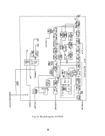
Page 40: ...28 Fig 4 1 Block Diagram RF PCB...
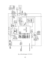
Page 41: ...29 Fig 4 2 Block Diagram CPU PCB...
Page 55: ...43 6 2 RAY210 ASSEMBLY DRAWING...
Page 57: ...45 6 3 SCHEMATIC DIAGRAM Fig 6 1 Schematic diagram RF PCB...
Page 58: ...46 Fig 6 2 Schematic diagram CPU PCB l...
Page 59: ...47 Fig 6 2 Schematic diagram CPU PCB 2...
Page 60: ...48 Fig 6 3 RF PCB Layout Top View...
Page 61: ...49 Fig 6 4 RF PCB Layout Rear View...
Page 62: ...50 Fig 6 5 CPU PCB Layout Top view...
Page 63: ...51 Fig 6 5 CPU PCB Layout Rear View...
Page 64: ...52...
Page 75: ...63...