


0049-1800-xxx 326X V.34, V.34-SDC and V.32bis Series Modem – USER’S GUIDE 02/23/2010
Rev. A
Page 168
of
205
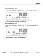
For an Illustration of the Enclosure Card Backplane …
Refer to the addendum,
326X Series Modem Cards
, shipped with the backplane.
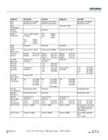
REAR PANEL INTERFACE PINOUTS
This section shows the rear panel interface pinouts for the modem stand-alone models 3260, 3261, 3265, and
3266, and enclosure card models 3262, 3263, 3267, and 3268.
Standalone Models 3260/65 and 3261/66 Interface Pinouts
This section shows the pinouts for the standalone modem’s rear panel connectors.
Dial Line Interface (Models 3260/3265)
Dial line connection is made via the DIAL LINE interface on the modem’s rear panel. Table C-1
describes DIAL LINE connector pinouts.
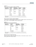
Table C-1.
Dial Line Interface (Models 3260/3265)
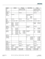
2-Wire Leased Line Interface (Models 3260/3265)
2-wire leased line connections are made via the DIAL LINE interface on the rear panel. Table C-2
describes 2-wire leased line interface pinouts.


