Site requirements
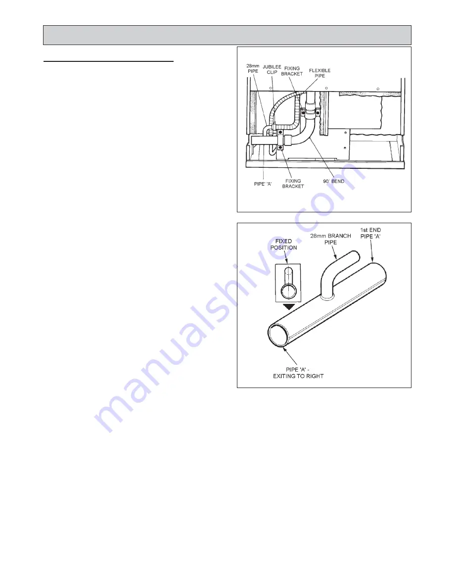
FLUE DIRECTION - EXIT TO THE RIGHT
Follow previous instructions in FLUE SYSTEM (Page 7),
Steps 1 to 3.
4.
Reposition the flexible tube from the oven vent down
the back of the oven.
5.
Smear sealant on the end of the manifold and replace
the bend.
6.
Smear sealant on the first end of pipe ‘A’ and the
surface of the 28mm branch (towards the bend). Slide
the flexible pipe completely over the branch (pipe
should point towards burner chamber).
7.
Push the first end of pipe ‘A’ onto the bend, the
branch should be above the pipe. Tighten the jubilee
clip ensuring the flexible pipe covers all of the branch
pipe.
8.
Replace brackets (4 screws).
9.
Replace back panel (7 screws).
8
FIG. 4
DESN 512669
DESN 512779
FIG. 5
Summary of Contents for XT
Page 20: ...20 Wiring Diagram FIG 21 WIRING DIAGRAM APPLIANCE ...
Page 22: ...22 ...
Page 23: ...23 ...


