16
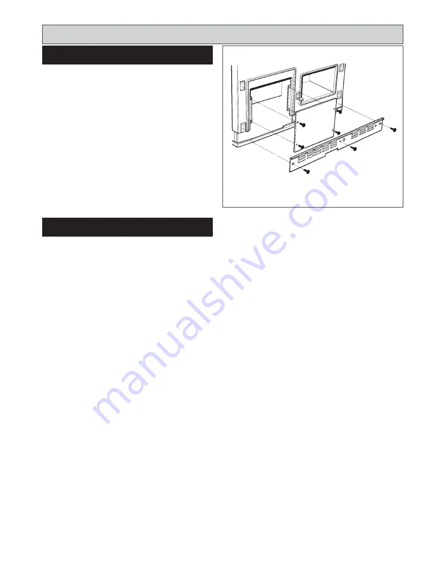
SEE FIG. 18
1. Open the burner access door.
2. Remove (4) inner panel securing screws and remove
panel.
3 Remove the (3) plinth securing screws and remove
plinth.
1. Make electrical connections to terminal strip as wiring
diagram (See Fig. 14)
Installation Instructions
FIG. 18
DESN 514110 B
BURNER ACCESS
ELECTRICAL CONNECTION
Summary of Contents for XT
Page 20: ...20 Wiring Diagram FIG 21 WIRING DIAGRAM APPLIANCE ...
Page 22: ...22 ...
Page 23: ...23 ...


