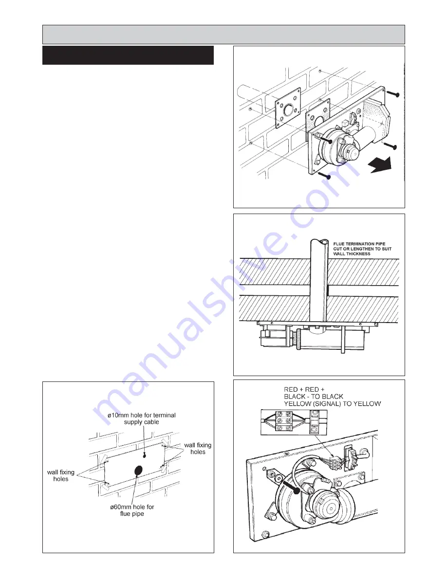
FIG. 10
DESN 513345
Site requirements
1.
Cut out card template from packaging and affix to
wall.
2.
Cut ø60 mm hole in the wall for the flue pipe. (See Fig.
10).
NOTE:
Larger holes are required through combustible
material.
3.
Drill 4 wall fixing holes through template (1 in each
corner. (See Fig. 10).
4.
Drill a minimum of a ø10 mm hole through the wall for
terminal supply cable.
5.
Remove card template and place flue terminal
assembly onto the hole. (See Fig. 11)
6.
The flue termination pipe may required to be
shortened or lengthened depending on wall thickness.
(See Fig. 12).
7.
Using the large wall fixings, permanently fix back plate
to the wall, removing outer cover first.
8.
Wire the fan to the supply cable to the terminal block
on the back plate. (See Fig. 13).
Using the 3-core cable provided, run cable back to flue
extractor circuit control at the bottom right hand side
of the appliance.
Red + to Red +
Black - to Black -
Yellow (Signal) to Yellow (Signal)
Replace outer cover onto terminal backplate.
9.
No additional flue terminal guard is required to this
appliance.
INSTALLATION
11
FIG. 12
DESN 512661
DESN 513350
FIG. 13
FIG. 11
DESN 513356
Summary of Contents for XT
Page 20: ...20 Wiring Diagram FIG 21 WIRING DIAGRAM APPLIANCE ...
Page 22: ...22 ...
Page 23: ...23 ...


