


46
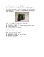
8 Optional Solid State Limit Switch
The optional limit switch for the transducer display provides 5 open collector Darlington outputs which are
switched on and off based on the position of the magnet on the transducer and the entered setup parameters.
8.1
Features
Five channels of Darlington transistor limit switch outputs
Integrated output transient protection
Removable screw terminals
8.2
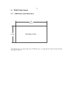
Mechanical Specifications
Mounts internal to the 1/8 din transducer display module.
8.3
Limit Switch Specifications
Five channels of Darlington transistor outputs with maximum of 50
VDC load
Maximum continuous collector current of 200 milliamps per channel
Peak collector current of 500 milliamps per channel
Maximum power dissipation for 5 channels of 1.5 watts at 70 degrees F
8 pin removable screw terminal
8.4
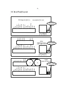
Solid state limit switch connections
Connections to the limit-switch output module are made through an 8 pin removable screw terminal to
connector J1. Connections to the analog output are made through connector J2.
8.5
Connector J1 Pin-out
J1-1: Limit Switch output 1
J1-2: Limit Switch output 2
J1-3: Limit Switch output 3
J1-4: Limit Switch output 4
J1-5: Limit Switch output 5
J1-6: Reserved
J1-7: Output transient protection voltage input
J1-8: Output common
8.6
Solid state limit switch output cautions
The Output transient protection voltage input (J1-7) should be connected to the relay or solenoid
supply voltage if relay coils or solenoids or other inductive devices are driven by the output. This input
takes the place of connecting a diode across the coil. In addition arc filters should be placed across the
contacts to suppress noise that can cause random problems with the display.


