background image

                                                                                  1 of 43                                                                    20111206 – Ver7                                             

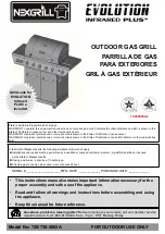
Hybrid Grill     

Infrared, Gas & Charcoal Cooking System   

Models Number:   
GR3055-014684     


ASSEMBLY & OPERATING INSTRUCTIONS


For Outdoor Use Only 


  This instruction manual contains important information necessary for the 

proper assembly and safe use of the appliance. 

  Read and follow all warnings and instructions before assembling/using 

the appliance. 

  Follow all warnings and instructions when using the appliance. 

  Keep this manual for further reference 

Summary of Contents for GR3055-014684

Page 1: ...ONS For Outdoor Use Only This instruction manual contains important information necessary for the proper assembly and safe use of the appliance Read and follow all warnings and instructions before ass...

Page 2: ...her appliance DANGER a Do not store a spare LP gas cylinder under or near this appliance b Never fill the cylinder beyond 80 percent full and c If the information in a and b is not followed exactly a...

Page 3: ...air DO NOT leave the grill unattended while in use DO NOT use while under the influence of drugs or alcohol Keep the fuel supply hose away from heated surfaces DO NOT put grill in storage or move it...

Page 4: ...k valve must have Type 1 outlet compatible with regulator or appliance Safety relief valve UL listed Overfill Protection Device OPD This OPD safety feature is identified by a unique triangular hand wh...

Page 5: ...ed with the cylinder valve Other types of caps or plugs may result in leakage of propane WARNING FOR FILLING THE LP GAS CYLINDER Allow only qualified LP gas dealers to properly fill or repair your LP...

Page 6: ...When connecting regulator assembly to the valve hand tighten the quick coupling nut clockwise to a complete stop Do not use a wrench to tighten Use of a wrench may damage the quick coupling nut and re...

Page 7: ...set to the OFF position 4 Turn on the fuel supply at the cylinder valve Turn the cylinder valve knob one turn counter clockwise 5 Apply the soap water mixture to the following a Supply tank weld b Con...

Page 8: ...body as far away from the burner as possible while lighting LIGHTING THE MAIN BURNER OF GRILL 1 Read all instructions before lighting 2 Open lid during lighting 3 Light the IGNITION BURNER first Push...

Page 9: ...lid is open 3 Place a lighted match between the coils on the extension rod and hold next to the burner 4 Turn the control knob s to the HI Light position Burner should light immediately 5 For infra re...

Page 10: ...r cat litter may be placed in the bottom of grease tray to absorb the grease Check the grease tray frequently Don t allow excess grease to accumulate in the grease tray Accumulated grease will easily...

Page 11: ...to the full OFF position 2 Turn the LP Gas tank valve to the full OFF position 3 Detach the LP Gas regulator assembly from your gas cylinder 4 Remove the Cooking Grates and Heat Distribution Plates fr...

Page 12: ...hanger into a small hook as shown and run the hook through the Burner Tube and inside the Burner several times to remove debris WARNING For safe operation ensure the Gas Valve Assembly Orifice is insi...

Page 13: ...ll for other than its intended purpose For household use only Do not use this grill for other than its intended purpose We recommend the use of a Charcoal Chimney Starter to avoid the dangers associat...

Page 14: ...ATION FOR USE LIGHTING INSTRUCTIONS WARNING OUTDOOR USE ONLY DO NOT OPERATE GRILL INDOORS OR IN AN ENCLOSED SPACE Never use grill indoors Carbon Monoxide poisoning can lead to death Curing your grill...

Page 15: ...fluid in grill and may result in a flash fire or explosion when lid is opened Step 5 Place lump or briquette charcoal on top of grate in chimney starter until full Underneath grate place balled up pa...

Page 16: ...ghting fluid approved for lighting charcoal Do not use gasoline kerosene alcohol or other flammable materials for lighting charcoal Follow all manufacturer s warnings and instructions regarding the us...

Page 17: ...nks or sticks Experiment by using more wood for stronger smoke flavor or less wood for milder smoke flavor Additional flavoring wood should not have to be added during the cooking process However it m...

Page 18: ...wear oven mitts gloves and carefully return charcoal tray to desired cooking level Extinguish any hot ashes coals or embers which may have fallen from doors or beneath and around grill Step 5 Close t...

Page 19: ...Rinse grates and dry completely using a towel Towel may become discolored This is normal 2 Apply a thin even coating of melted shortening Crisco as an example to the grates with a soft cloth or paper...

Page 20: ...20 of 43 20111206 Ver7 Product diagram...

Page 21: ...urner Hanger Qty 1 pc Qty 1 pc Qty 1 pc Qty 2 pcs 9 Grill Handle 10 Side Burner 11 Side Burner Lid Handle 12 Side Burner Control Panel Qty 1 pc Qty 1 pc Qty 1 pc Qty 1 pc 13 Side Burner Cooking Grate...

Page 22: ...Grease Cup 30 Leg Adjuster 31 Lower Lid Hinge 32 Upper Lid Hinge Qty 1 pc Qty 2 pcs Qty 4 pcs Qty 4 pcs 33 Air Vent 34 Side Burner Grease Tray 35 Charcoal grease tray handle 36 Burner Knob Qty 1 pc Qt...

Page 23: ...m name Diagram Qty A M6 X 35mm Bolt Black 16 B M6 X 15mm Bolt Black 4 C M6 X 12mm Bolt Black 33 D M6 X 12mm Bolt Sliver 2 E M5 X 10mm Bolt Black 26 F M6 X 12mm Hexagonal Bolt 4 G M6 Locking Nut 1 H M1...

Page 24: ...24 of 43 20111206 Ver7 Hardware List K M6 Cap Nut 2 L Cotter Pin 4 M Wing Screw 1 N Spring 1 O Insulation Washer 4 P M10 Washer 1 Q M12 Washer 2 R Hinge Pin 4 S Screwdriver 1 T Hex Nut Wrench 1...

Page 25: ...Ver7 Assembly Procedures Step 1 Attach Left Wheel Leg 17 and Right Wheel Leg 18 on Left Shelf 23 as shown by using 4 pcs of M5x10mm Bolts E Step 2 Attach the Left Leg Panel 21 as shown by using 6 pcs...

Page 26: ...Wheels 27 and M12 Washer Q Use the Hex Nut Wrench T to fasten on the left leg After the Wheel Axle is secured attach the Wheel Cover 39 on the wheel Step 4 Attach the Right Pivot Leg 20 and Left Pivot...

Page 27: ...27 of 43 20111206 Ver7 Step 5 Attach the Right Shelf 24 as shown and secure with 4 pcs of M6x12mm Bolts C Step 6 Attach the Shelf Brace 28 on the right leg as shown using 8pcs of M5x10mm Bolts E...

Page 28: ...provides the function of grill leveling adjustment Step 8 Connect the left and right leg units together using the Cart Brace 26 as shown using 8 pcs of M6x12mm Bolts C Be sure that the Left Leg Panel...

Page 29: ...unit The grill body and leg unit is secured by 6 pcs of M6x12mm Bolt C as shown Step 10 Attach two Upper Lid Hinges 32 to the back of EACH lid as shown using 8 pcs of M6x35mm Bolts A and M6 Nuts I At...

Page 30: ...Lower Lid Hinge 31 together using the Hinge Pin R and Cotter Pin L as shown Note that the lid 2 has a chimney hole on the right side ie Charcoal chamber Step 12 Open each lid Attach the Lid Handle 2...

Page 31: ...irst insert the Charcoal Door Knob 5 through the door hole M10 Washer P and Charcoal Door Lock Plate 7 The locking unit is secured by M10 Locking Nut H Note Grip The Charcoal Door Knob 5 with HAND ONL...

Page 32: ...tep 15 Open the lid at charcoal chamber Attach the Air Vent 33 with an M6x12mm screw C and M6 Locking Nut G as shown Step 16 Attach the Grill Handle 9 to the right side of grill body using 4 pcs of M6...

Page 33: ...ft side of grill body by using 4 pcs of M6x12mm Bolt C and M6 Nut I Attach the Gas Tank Block Bar 37 to the lower left side of grill body by using a Wing Screw M Step 18 Open the Side Burner 10 lid at...

Page 34: ...20111206 Ver7 Step 19 Attach the Side Burner 10 onto the Side Burner Hanger 8 as shown in diagram below Step 20 Secure the Side Burner 10 in place by inserting 2pcs of M6x12mm Bolts C into holes A B...

Page 35: ...o the side burner as shown in illustration 1 and 2 2 Insert the thermocouple into the hole on the left hand side on the fixing piece The pre attached bolt is well at the middle hole on the fixing piec...

Page 36: ...ttach the Side Burner Control Panel 12 on the Side burner valve as shown in illustration 1 and 2 As shown in illustration 3 hold the valve in position and move up slightly per step 01 then fasten the...

Page 37: ...Step 24 Attach the Control Panel 12 on the side burner NOTE Do don t over twist tubing and wires of this unit during the assembly Step 25 Fasten the Side Burner Control Panel 12 by using 2 pcs of M6x...

Page 38: ...Attach the Burner Knobs 36 on each burner valve Step 27 Pull out the charcoal grease tray which has been placed at the grill body bottom on the back side Attach the Charcoal Grease Tray Handle 35 by...

Page 39: ...Side Burner Cooking Grate 13 Step 29 Place the Heat Distribution Plate 25 and Gas Grill Cooking Grate 15 in the gas grill chamber These Gas Grill Cooking Grates are coated with porcelain Also place t...

Page 40: ...cks 14 into each grill chamber as shown These warming racks are secured by 2 pcs of M6 Cap Nut K and 2 pcs of M6 Nut I Step 31 Remove the pre attached nut from Thermometer 42 Attach the thermometers o...

Page 41: ...41 of 43 20111206 Ver7 Step 32 Install the Grease Cup 29 to the back of gas grill chamber Step 33 Install the Side Burner Grease Tray 34 to the bottom of side burner 34...

Page 42: ...42 of 43 20111206 Ver7 Step 34 The Cooking Grate Lifter 43 is provided for taking out the cooking grate if needed Congratulations Assembly is Complete...

Page 43: ...GATION Manufacturer s liability shall be limited to the delivery of a good merchantable Product and if necessary the repair or replacement at manufacturer s option of any defective part or unit 7 TRAN...

Reviews: