


26
●
to check calibration of the scanner
●
If the reference grid of 3D-marks is already created - load it through File → Load reference grid
●
at a working distance from the scanner
●
Turn on
Stripes and lines mode,
check the sharpness of the projector and with the help of the
of cameras
●
Start scanning with the corresponding button
●
Scan the object in the next position, visually observing the correctness of fragments stitching in
the 3D model viewing area. If the scan during stitching is in obviously incorrect position, it is clear
that such scan should be deleted - select it in the tree and press Delete.
●
Go to ScanMerge for further processing or create a new project to scan the object from the other
side.
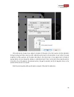
Identified markers may appear in the following colors:
Yellow
Marker found only once (not reliable)
Green
Marker found on several scans (reliable)
Red
Marker of the reference grid
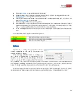
Options
Options
menu displays the properties of the
project. Depending on the type of the project, the
number of options may vary.
When scanning without markers
in
Settings
you
may change the parameters for interception of the
model by planes. The scanner is building a 3D model
only of those parts of the object, which fall into the
area, limited by near-end and far-end clipping border. For example, if far-end and near-end borders are 200
and -200mm respectively, and the scanner is configured to the scan zone 2 with working distance of about
40cm, the model would be constructed only in the area of 20 - 60 cm from the scanner.
When scanning with markers
besides the above mentioned parameters in
Settings
you may also specify
marker properties. When using customized markers, specified their radius in the corresponding field.