background image

INSTALLATION

Check the appliance is electrically safe and gas sound when you have finished.

21

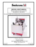
ArtNo.010-0004 Moving the cooker

ArtNo.110-0010 Fitting the stability bracket 

550 mm

100 mm

550 mm

ArtNo.010-0010 Lowering the rear rollers (90) 

x10

Fig.7-6

Fig.7-7

Fig.7-8

A - Wall face,   B - Rear rollers,   C - Front levelling feet,    

D - Pencil datum line

ArtNo.010-0002 Rear roller nut 

Fig.7-5

Fig.7-9

A - Back of cooker,   B - Stability bracket 

Lowering the Two Rear Rollers

First fit the levelling tool on the hexagonal adjusting nut 

(Fig.7-5). Make 10 complete (360º) turns clockwise (Fig.7-6)

(This means turning and removing the levelling tool 20 

times).
Make sure you lower BOTH REAR ROLLERS. There are two 

adjusting nuts, one for each roller, at both the front bottom 

corners of the cooker.

Completing the Move

Unfold the rear edge of the pack base tray. Open the grill 

door and right-hand oven door so that you can get a good 

grip on the bottom of the fascia panel as you move the oven 

(Fig.7-7).
Carefully push the cooker backwards off the pack base. 

Remove the pack base tray.
Position the cooker close to its final position, leaving just 

enough space to get behind it.

n

n

Do not use the door handles or control knobs to 

manoeuvre the cooker.

Fitting a Stability Bracket

A stability bracket or chain (not supplied by with the cooker) 

should be fitted when the cooker is connected to a flexible 

gas supply.
When fitting a stability bracket, read these instructions 

together with the leaflet supplied with the bracket.

1. 

Place the cooker in its intended position and level the 

cooker.

2. 

Draw a pencil line 70 mm from the front edge of the 

levelling feet.

3. 

Mark the centre line for the bracket by measuring 

550 mm from the left-hand side of the cooker.

4. 

Move the cooker forward.

5. 

Measure back from the pencil line 550 mm to locate the 

front edge of the bracket (Fig.7-8).

6. 

Position the bracket so that it is away from centreline of 

the cooker to reduce the possibility that it will trap the 

electrical connection cable or gas hose.

7. 

Fix the bracket to the floor.

8. 

Measure the height from floor level to engagement 

edge in back of cooker. Add 3 mm to this dimension and 

assemble the stability bracket to this height (i.e. from 

floor level to underside of the top member), and ensure 

the bracket does not foul the oven burner assembly 

(Fig.7-9).

Summary of Contents for Classic 110 110 Dual Fuel FSD

Page 1: ...Elite 110 Dual Fuel FSD User Guide Installation Instructions U106000 09A ArtNo 000 0005 Classic logo...

Page 2: ...g Table 15 6 Troubleshooting 16 7 Installation 18 Dear Installer 18 Safety Requirements and Regulations 18 Provision of Ventilation 18 Location of Cooker 19 Conversion 19 Positioning the Cooker 20 Mov...

Page 3: ...the room is well ventilated to the outside air see Ventilation below People with respiratory or allergy problems should vacate the area for this brief period If you smell gas DO NOT turn electric swi...

Page 4: ...ture on fresh foods can cause hot fat to bubble up and over the sides of the pan Carefully watch for spills or overheating of foods when frying at high or medium high temperatures Never try to move a...

Page 5: ...that prevents the flow of gas if the flame goes out When the igniter button is pressed in sparks will be made at every burner this is normal Do not attempt to disassemble or clean around any burner w...

Page 6: ...e pan supports You should also avoid using unstable and misshapen pans that may tilt easily and pans with a very small base diameter e g milk pans single egg poachers Fig 2 7 The minimum recommended p...

Page 7: ...wooden utensils n n DO NOT put it crossways it will not fit properly and will be unstable n n DO NOT put it on any other burner it is not designed to fit in any of the other pan supports Position the...

Page 8: ...rivet can be removed and the food placed on it while you are waiting for the grill to preheat Once the grill has preheated slide the grill pan out again With the trivet back in place with the food on...

Page 9: ...too quickly so we recommend that the food be positioned in the lower half of the oven to cook The oven temperature may also need to be lowered Similar items being cooked will need to be swapped aroun...

Page 10: ...ng The cook period which is the length of time you want the oven to cook for The stop time which is the time of day you want the oven to stop cooking To stop the ovens automatically Press and hold the...

Page 11: ...med by the display showing the time of day alongside the key symbol Fig 2 33 To turn off the key lock Hold the Minute Minder and Cook period buttons When OF appears on the display Fig 2 34 press the b...

Page 12: ...n Part Code RM027 It can be fitted at two different heights One of the oven shelves must be removed and the other positioned to suit When the Handyrack is used in its highest position other dishes can...

Page 13: ...ith the front edge of the oven s wire shelves Other containers should be placed centrally Keep all trays and containers away from the back of the oven as overbrowning of the food may occur For even br...

Page 14: ...5 50 minutes per 500g of mixture 2 2 hours Up to 3 hours 80 90 minutes 15 25 minutes 10 15 minutes 20 30 minutes 30 40 minutes 20 30 minutes on a preheated tray 35 45 minutes 10 20 minutes according t...

Page 15: ...ker or our website www rangemaster co uk Hotplate Burners Some models have a separate trim ring which fits on the burner head The burner heads and caps can be removed for cleaning Make sure they are a...

Page 16: ...the Moving the Cooker section under Installation Open the oven door slightly and remove the front panel fixing screws from the door sides two each side Fig 5 5 Carefully lift off the outer door panel...

Page 17: ...ol Wash in hot soapy water Do not use abrasive cleaners scourers Dishwasher Warming zone some models only Toughened glass Hot soapy water cream cleaner scourer if necessary Outside of cooker Part Fini...

Page 18: ...l installer 6 Troubleshooting Power failure In the event of a failure in the electrical supply remember to reset the clock to ensure that the timed oven continues to operate Food is cooking too slowly...

Page 19: ...our fingers with a glove in case the bulb should shatter unscrew the old bulb Screw in the new bulb screw back the bulb cover Turn on the circuit breaker and check that the bulb now lights The oven do...

Page 20: ...the Republic of Ireland the cooker must be installed in accordance with The installation must be carried out by a competent person and installed in accordance with the current edition of IS 813 Domes...

Page 21: ...You will need the following equipment to complete the cooker installation satisfactorily Stability bracket If the cooker is to be supplied with gas through a flexible hose a stability bracket or chai...

Page 22: ...r damage caused by normal use of the cooker to any material that de laminates or discolours at temperatures less than 65 C above room temperature We recommend a gap of 1110 mm between units to allow f...

Page 23: ...ay Position the cooker close to its final position leaving just enough space to get behind it n n Do not use the door handles or control knobs to manoeuvre the cooker Fitting a Stability Bracket A sta...

Page 24: ...on a shelf in one of the ovens to check for level Place the cooker in its intended position taking care not to twist it within the gap between the kitchen units as damage may occur to the cooker or th...

Page 25: ...should be fitted so that both inlet and outlet connections are vertical so that the hose hangs downwards in a U shape Ideally the hose supply connection should be within the shaded area A shown Fig 7...

Page 26: ...cess to the mains terminal is gained by removing the electrical terminal cover box on the back panel Connect the mains cable to the correct terminals for your electrical supply type Fig 7 14 Check tha...

Page 27: ...and heads Remove the old jets Fig 8 1 Fit the new jets see Technical Data section at the back of the book for correct jets Reassemble in the reverse order Tap adjustment Pull off all the control knobs...

Page 28: ...or Orange r Red v Violet w White y Yellow g y Green yellow gr Grey 9 Circuit Diagram Code Description A1 Grill control A2 Grill element left hand side A3 Grill element right hand side B1 Left hand ove...

Page 29: ...Injector Screw Injector Screw Wok burner 3 65 kW internal 80 96 3 5 kW 246 g h internal 54 57 external 129 external 77 Large burner 3 0 kW 134 54 3 0 kW 210 g h 87 40 Medium burner 1 7 kW 109 39 1 7 k...

Page 30: ...28...

Page 31: ...29...

Page 32: ...er co uk Clarence Street Royal Leamington Spa Warwickshire CV31 2AD England Tel 44 0 1926 457400 Fax 44 0 1926 450526 E mail consumers rangemaster co uk ArtNo 000 0003 CE logo DocNo 000 0001 Back cove...

Reviews: