


Measurement Principles
R&S
®
RT-ZS60
26
User Manual 1418.7342.02 ─ 04
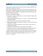
Figure 4-1: Equivalent circuit model of the R&S
RT-ZS60 probe
Table 4-1: Designations
Abbreviation
Description
V
S
Voltage at the test point without probe connected
V
in
Voltage at the test point with probe connected,
corresponds to the input voltage of the probe
R
S
Source resistance of the DUT
R
L
Load resistance of the DUT
R
in
DC input resistance
C
in
RF input capacitance of the probe
C
LF
LF input capacitance of the probe
R
RF1
, R
RF2
RF input resistance of the probe
L
con
Parasitic inductance of the ground connection
In a 50
Ω system, the output resistance of the source, the load resistance and the
characteristic impedance of all lines equal exactly 50
Ω. However, the behavior of
the probe in the circuit is determined by the effective source impedance which is
the impedance present in the DUT between the probe tip and ground.
Effective source impedance:
25
||
L
S
S
R
R
R


