


Measurement Principles
R&S
®
RT-ZS60
30
User Manual 1418.7342.02 ─ 04
4.1.3
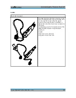
Performance with Different Connection Types
The
Table 4-2
shows three types of connection between probe and DUT as well
as the associated rise times, bandwidths, input impedances and overshoots.
Table 4-2: Typical rise time, bandwidth, input impedance and overshoot with different
connection types
No
Connection
Type
Connection
Rise
time
Band-
width
Min. input
impedance
|Z
min
|
Over-
shoot
Signal
socket
Ground
socket
1
signal
pin
ground
pin,
pogo
wide
spacing
64
ps
6
GHz
150
Ω
9
%
narrow
spacing
55
ps
8
GHz
110
Ω
25
%
2
signal
pin, sol-
der in
ground
pin, sol-
der in
short
pins
66
ps
6.5
GHz
155
Ω
8
%
long
pins
70
ps
4.5
GHz
235
Ω
11
%
3
signal
adapter,
square
pin
ground
adapter,
square
pin
wide
spacing
64
ps
5.5
GHz
120
Ω
11
%
narrow
spacing
52
ps
9
GHz
75
Ω
34
%
Signal Integrity of the Transferred Signal


