background image

Frame

Boss

Instruction Manual

Standard Operating Procedure

Note: Refer to safety precautions before attempting to operate the tool.

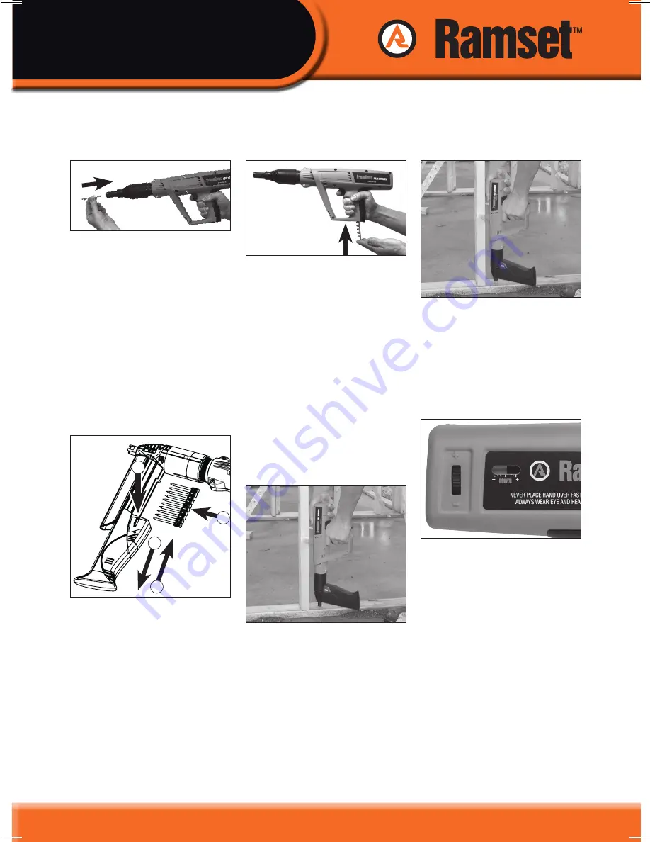
4. Fire the tool.

Press the fastener guide firmly 
against the work surface, 
Call `FIRING’ to alert those 
nearby, and pull the trigger. 

5. Check the fastener has 

been correctly set. 

(See Fastener Setting, page 9) 

3. Take up the correct firing 

stance. 

Make sure the tool is at right 
angles (90º) in both directions 
to the work surface. Your body 
should be directly behind the 
tool in a balanced posture. 

6. Adjust the power, if 

necessary.

Increase power by increasing 
power setting. When maximum 
setting is reached, move wheel 
back to minimum position and 
insert next strength power load.

7. Repeat steps 1,3,4,5 and 6 

for the next fixing point.
8. repeat step 2 after every 

10 fixings.

1b. Tool fitted with fastener 

magazine.

1 - Press the magazine release 

button.

2 - Slide the magazine cover 

down.

3 - Insert Ramset™ collated 

drive pins.

4 - Push the magazine cover 

back into the closed 
position.

2

4

3

1

2. Insert the power load.

With the tool in the closed 
position insert a power load 
strip into the cavity in the base 
of the rubber handle and push 
it in until the flat of your finger 
tip is firmly against the handle 
recess. The first power load is 
now aligned with the chamber 
prior to cocking. 

note:

 Always use the lowest 

strength power load and lowest 
power setting first, for a firing 
test, then adjust the power to 
suit the job. 

PUSH

1. Select and insert the 

fastener.

Select the correct fastener for 
the application (see Fastener 
Selection, page 7). Point the tool 
down and away from yourself 
and any other person. 

1a. Tool fitted with single 

shot fastener guide.

Insert a fastener, HEAD FIRST 
into the fastener guide at the 
front end of the tool, making 
sure the fastener guide stays in 
the forward position.

PUSH

10

Summary of Contents for FrameBoss pat003

Page 1: ...or specific training may be required Your Ramset supplier can advise you on this matter Except as required by statute the manufacturer disclaims all responsibility for any incidents which may result f...

Page 2: ...FrameBoss Instruction Manual...

Page 3: ...Selection 7 Power Load Selection 8 Fastener Setting 9 Standard Operating Procedure 10 Trouble Shooting 11 Drive Pin Fastener Removal 12 Inspection Tool Maintenance 13 Site Preparation 14 Tool Inspecti...

Page 4: ...FormMaster FrameMaster TS750P JobMaster TyMaster FixMaster TS60P Rocket InsulFast and DekMaster use the new low velocity indirect acting system to deliver a powerful strike on the fastener The low ve...

Page 5: ...pressed against the work surface and the tool does not fire Refer to page 5 for instructions to follow in the event of a misfire Powder Actuated P A Simply means the energy to drive the fastener is pr...

Page 6: ...ng place 6 metres Warning NEVER PLACE HAND OVER FASTENER GUIDE ALWAYS WEAR HEARING AND EYE PROTECTION Always check the barrel is free of obstructions before loading Always call FIRING immediately befo...

Page 7: ...consistently Return tool to Ramset immediately for inspection service In these circumstances NEVER send these items through the post What to do if a P A Tool Jams In the event that a tool becomes jam...

Page 8: ...nless for fastening into thinner steel the shank diameter of the fastener is less than the thickness of the steel Never use wood fibreboard plaster or any soft material including mortar as the base ma...

Page 9: ...ding 6mm to allow for full penetration For steel over 8mm the required length is calculated by adding 12mm to the fixture thickness Attaching fixtures to concrete It is important for the drive pin or...

Page 10: ...s required to obtain a suitable fixing Other Power Controls The FrameBoss Rocket FrameMaster TS750P FixMaster TS60P and FormMaster tools also have the feature of variable power adjustment This provide...

Page 11: ...or adjusting the power setting if applicable If the fastener is under driven by a tool with power adjustment increase the power by increasing the power setting until a suitable fixing is achieved If t...

Page 12: ...ed with fastener magazine 1 Press the magazine release button 2 Slide the magazine cover down 3 Insert Ramset collated drive pins 4 Push the magazine cover back into the closed position 2 4 3 1 2 Inse...

Page 13: ...ip damaged Problem with tool or faulty charge power load Damage to power load chamber Cartridge strip damaged Strip index mechanism damaged Tool overheated fastening rate too high Hot tool compressed...

Page 14: ...id material Ramset recommends that they should be removed broken with a Ramset Pin Breaking Tool Part Number PBT The use of a Ramset Pin Breaking Tool ensures that all fragments of a drive pin are con...

Page 15: ...l The Australian Standard AS1873 states that all Powder Actuated P A Tools be returned to the manufacturer or its authorised agent for a complete overhaul at least once in every 12 month period 2 Hold...

Page 16: ...m thick 7 Using the supplied wire brushes thoroughly clean all internal and external steel surfaces of any carbon buildup 8 Lightly oil the internal steel components with Ramset P A lubricant PA9316 a...

Page 17: ...verall length 490mm 495mm with magazine Technical Data FrameBoss TM Ramset tools fasteners charges and other components of the Ramset Fastening System are designed and manufactured as a complete syste...

Page 18: ...Pins for concrete masonry and steel Part No Drive Pin Length Max Fixture Max Fixture Pack Qty thickness to steel thickness to concrete C925C 25mm 12mm 2mm 500 C930C 30mm 20mm 7mm 500 C940C 40mm 25mm 1...

Page 19: ...m 200 Product Range Drive Pins for fixing thin steel to steel Part No Description Drive Pin Length Pack Qty SP12 Heavy Duty Pin 13mm 100 Product Range Washered Drive Pins for Concrete Masonry Part No...

Page 20: ...ton Return Spring x1 5 010983 Piston Buffer x2 6 PA37037 Piston 7 PA37007 Barrel Assembly 8 N A Rear Tool Assembly 2 3 4 7 Item No Spare Part No 1 PA37023 Spall Guard Not Shown 2 PA37063 Fastener Guid...

Page 21: ...FrameBoss Instruction Manual 5 6 8 19...

Page 22: ...stration Firing a Powder Actuated P A tool When demonstrating the correct use of a P A Tool the instructor will be looking for the following key skills Preparation including erecting checking warning...

Page 23: ...ng other than the work surface 5 What MUST be done in the event of a misfire 6 What MUST be done in the event of repeated misfires by the same tool 7 What MUST be done in the event of a tool jam 8 Wha...

Page 24: ...FrameBoss Instruction Manual FrameBoss TM Tool Service Log Records Model Number Purchased from Date Serial Number Purchaser s Name Company Name Address Signature Trade 22...

Page 25: ...FrameBoss Instruction Manual FrameBoss TM Tool Service Log Records con t Date Type of Service Hours Details of service Status Signature Used Show components replaced 23...

Page 26: ...FrameBoss TM Tool Service Log Records con t Date Type of Service Hours Details of service Status Signature Used Show components replaced FrameBoss Instruction Manual 24...

Page 27: ...d to Ramset Model Number Serial Number Purchased from Date I agree that the terms set out in the Warranty shall apply to the sale and purchase of the product described above Purchaser s Name Phone Fax...

Page 28: ...o and not in substitution for any rights of the purchaser arising under the Trade Practices Act 1974 or any relevant legislation for any States and Territories of the Commonwealth of Australia providi...

Reviews: