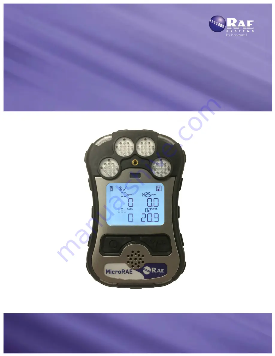
MicroRAE
TM
Wireless Personal Four-Gas Monitor
Rev. A
January 2016
P/N M03-4002-000
Page 1: ...MicroRAE TM Wireless Personal Four Gas Monitor Rev A January 2016 P N M03 4002 000...
Page 2: ...ct online by visiting http www raesystems com support product registration By registering your product you can Receive notification of product upgrades or enhancements Be alerted to Training classes i...
Page 3: ...E Off 21 7 3 Testing Alarm Indicators 22 7 4 Glance Mode 22 7 4 1 Enter Glance Mode 22 7 4 2 Screens 23 7 4 3 Exit Glance Mode 23 8 Modes Of Operation 26 9 Programming 26 9 1 Enter Programming In Basi...
Page 4: ...ibration 41 11 2 2 Single Sensor Zero Calibration 41 11 3 Span Calibration 42 11 3 3 Multi Sensor Span Calibration 42 11 3 4 Single Sensor Span Calibration 42 12 Datalog Transfer Monitor Configuration...
Page 5: ...performance of this product Warning Substitution of components may impair safe performance of this product SPECIAL CONDITIONS FOR SAFE USE This multi gas monitor must be calibrated if it does not pass...
Page 6: ...CHAQUE UTILISATION JOURNALIERE VERIFIER LA SENSIBILITE AVEC UNE CONCENTRATION CONNUE DE METHANE EQUIVALENTE A 20 50 DE LA PLEINE ECHELLE LA PRECISION DOIT ETRE COMPRISE ENTRE 0 20 DE LA VALEUR VRAIE E...
Page 7: ...tissement La substitution de composants peut compromettre la securit intrins que WARNING Read and understand instruction manual before operation or servicing AVERTISSEMENT Lisez et comprenez le manual...
Page 8: ...rom general or household waste Please use the return and collection system available in your country for the disposal of this product Sensor Specifications Cross Sensitivities And Calibration Informat...
Page 9: ...with the accessories shown below In addition to the instrument the following are included Item Part Number Travel charger M03 3005 000 AC adapter 500 0036 102 USB cable 410 0203 000 MicroRAE CD M03 4...
Page 10: ...eadings and alarm status from any location for better visibility and faster response 2 1 Key Features All in one continuous monitoring capabilities for oxygen toxic and combustible gases for a total o...
Page 11: ...dio or WiFi Wireless status the radio is on replaced by R when Roaming is on Wireless strength is indicated by 0 to 4 bars Flashing icon without bars indicates network has not been found Cannot find n...
Page 12: ...es 9 to 12 satellites Datalogging status shown when datalogging is on blank when off Battery voltage is greater than 70 Battery voltage is 41 to 70 Battery voltage is 11 to 40 Battery voltage is less...
Page 13: ...o menu each key controls a different parameter or makes a different selection In addition to the functions described above either key can be used to manually activate display backlighting Press a key...
Page 14: ...The display shows the message sequentially cycling through the message each half second The Message number page of the message it automat ically breaks a message across screens and received time and...
Page 15: ...automatically 3 5 Panic Alarm Press and hold Y at any time to trigger the Panic Alarm The display shows PANIC ALARM and sends a message to the Location Manager or ProRAE Guardian Note Use ProRAE Stud...
Page 16: ...e Menus diagram there are four screens for wireless communication containing information on wireless settings and status If Roaming is not turned on then you must set a PAN ID in order to communicate...
Page 17: ...heres recharge remove or replace the battery only in an area known to be non hazardous Next put the plug from the power supply P N 500 0036 102 into the jack on the side of the Travel Charger Plug the...
Page 18: ...wer supply into the jack on the side of the Multi Charger Plug the other end of the charger into a power source 5 1 1 Charging With The Multi Charger Press the MicroRAE into any of the Multi Charger s...
Page 19: ...MicroRAE User s Guide 19 Remove the instrument from the cradle by tilting the release on the rear of the charging cradle away from the instrument and lifting the MicroRAE...
Page 20: ...age the instrument warns you by beeping once and flashing once every minute The instrument automatically powers down within 10 minutes after which you will to recharge the battery 6 External Filter Th...
Page 21: ...des data if you turn a sensor off and on again it also shows for up to 45 seconds Then it displays instantaneous readings similar to the following screen depending on the sensors installed and is read...
Page 22: ...s etc which may help when taking inventory of instruments and their sensors or when working with service or support personnel Glance Mode can be enabled disabled via ProRAE Studio II 7 4 1 Enter Glanc...
Page 23: ...Note Remote notification requires wireless connection to a network Whenever the Man Down feature is on the main screen displays a Man Down icon along the top to indicate it is active IMPORTANT When g...
Page 24: ...esses MODE during the countdown answering the OK question by pressing MODE for No the Man Down alarm starts If wireless connectivity is enabled and the QRAE 3 is connected to a network a Man Down mess...
Page 25: ...sensor requires a bump test then Bump Overdue icon is shown by the sensor name in the display A bump test is required if the defined period of time between bump tests has been exceeded This interval i...
Page 26: ...g ProRAE Studio II and having administrative privileges For a list of which parameters can be set in Programming Mode on the MicroRAE in ProRAE Studio II or both 9 1 Enter Programming In Basic Mode 1...
Page 27: ...3 Menus And Submenus In Programming Mode menus and submenus are organized as shown here Calibration Sensor On Off Clear Datalog Monitor Setup Set Radio Single Bump Sensor 1 On Off GPS On Off BLE On Of...
Page 28: ...rated in clean ambient air with 20 9 oxygen 02 For more precise low 02 percentage accuracy and after a new 02 sensor is put into the instrument zeroing should be performed with nitrogen N2 A zero cali...
Page 29: ...e zero calibrated in clean ambient air with 20 9 oxygen A fresh air calibration should precede a span calibration The selected sensors are shown on the screen Start a multiple zero test by pressing Y...
Page 30: ...e recovered Note The datalog is password protected You must enter the correct password in order to clear the datalog 1 Enter the password the default value is 0000 2 Press Y The message Log Cleared ap...
Page 31: ...gs that can be changed Note BLE Bluetooth Low Energy is included in all MicroRAEs 9 3 5 1 BLE On Off You can turn BLE in all configurations of MicroRAE or turn WiFi or Mesh Roaming depending on how yo...
Page 32: ...esh Radio The MicroRAE and any other devices that you want to connect wirelessly must be operating on the same channel Note For radio modems operating at 868MHz only channel 0 is available For other f...
Page 33: ...ore all the wireless settings to their original factory defaults Caution Once you reset the wireless settings you cannot retrieve any of the settings deleted by performing this reset Press Y to initia...
Page 34: ...enable disable any combination of light LEDs buzzer and vibration alarms Settings All Enabled Lights Only Vibration Only Buzzer Only Buzzer Light Buzzer Vibration Vibration Light All Disabled 9 4 1 3...
Page 35: ...e either automatically based on ambient light conditions or manually or it can be shut off In addition you can view or change the Back Light Trigger Value 9 4 1 11 Messaging Get or set pre configured...
Page 36: ...ke your selections Sensors to Log You can select which sensors you want included in your datalogs Use the check boxes to make your selections Sensor Maintenance After a new sensor is installed list it...
Page 37: ...tup routine 2 Press MODE until Comm Mode is displayed 3 Press Y The screen now displays Ready To PC 4 Start ProRAE Studio II 5 Select Administrator 6 Input the password the default is rae 7 Click OK 8...
Page 38: ...con labeled Upload current settings to the instrument 14 A confirmation screen is shown Click Yes to perform the upload or No to abort Uploading takes a few seconds and this progress bar is shown You...
Page 39: ...osure to poisons and contaminants Calibration intervals and bump test procedures may vary due to national legislation A bump test can be performed either manually or using the AutoRAE 2 Automatic Test...
Page 40: ...rming a bump test The instrument will take the time to warm up the sensors prior to enabling access to bump test menus You can tell a sensor has warmed up if you see a reading next to it name on the d...
Page 41: ...ration Adapter Using a calibration adapter is not necessary for calibration in fresh air 11 2 1 Zero Calibration This procedure determines zero points of most sensors The MicroRAE should be zero calib...
Page 42: ...nsors 11 3 3 Multi Sensor Span Calibration This lets you perform a span calibration on multiple sensors simultaneously It requires using the appropriate span gas and that the concentration labeled on...
Page 43: ...ODE After a timer countdown the span calibration is done The LCD will display whether the calibration was successful and the reading for that calibration gas Note If the sensor calibration fails try a...
Page 44: ...l Charger and must be in the PC communications mode 1 Use the supplied PC Communications Cable USB to mini USB cable to connect the Travel Charger to a PC 2 Turn on the MicroRAE Make sure it is runnin...
Page 45: ...sensors in hazardous locations All sensors are located inside the sensor compartment in the upper half of the MicroRAE To access the sensors 1 Turn off the instrument 2 Remove the four screws in the b...
Page 46: ...r 3 Replace the cover and tighten the four screws WARNING It is extremely important that sensors are installed in the correct orientation When installing a new sensor the plastic film should be on top...
Page 47: ...tomer service Before mating the front and back housings make sure the Sealing Rib is in position and not cracked damaged or distorted The four screws that hold the housing together must have new O rin...
Page 48: ...gas concentration is compared with the programmed alarm limits for Low High TWA and STEL alarm If the concentration exceeds any of the preset limits the alarms are activated immediately to warn both t...
Page 49: ...p sec TWA at sensor location ALARM icon on 400ms Blinking reading On Calibration Failure 1 beep sec CAL at sensor location ALARM icon on 400ms Blinking reading On Bump Failure 1 beep sec Bump at senso...
Page 50: ...s are enabled but not functional the instrument should not be used Contact RAE Systems Technical Support Alarm Type Buzzer LED Display Vibrator Reading Backlight Priority Oxygen Low Low 3 beeps second...
Page 51: ...cess for changing settings The MicroRAE s Diagnostic Mode can only be accessed at startup time In Diagnostic Mode MicroRAE displays readings in raw counts instead of units such as parts per million pp...
Page 52: ...tion 2 ID and Gain press Y to step through raw count and last calibration date and time Buzzer Mode press Y to change 0 silent 1 through 7 indicates number of beeps per second Buzzer Frequency press Y...
Page 53: ...an Set LEL Calibration Gas Set Span Sensor On Off Set LEL Measurement Gas Set Alarm Limits Set Alarm Mode Alarm Settings Comfort Beep Man Down Alarm On Off Man Down Alarm Motionless Time Man Down Sens...
Page 54: ...ss Set Server Port Confidence LED interval Get Set bump test date and interval Get Set calibration test date and interval Get Set sensor maintenance Get Set sensor to log Set Glance Mode screen Roamin...
Page 55: ...nd programming keys MODE and Y Sampling Diffusion Calibration Manual Alarms Wireless remote alarm notification audible vibration visible flashing bright red LEDs and on screen indication of alarm cond...
Page 56: ...ject to change Sensor Specifications Combustible Sensor Range Resolution Operating Temperature Catalytic bead LEL 0 to 100 LEL 1 LEL 4 to 122 F 20 to 50 C Electrochemical Sensors Range Resolution Oper...
Page 57: ...e Month Second digit Month code 2014 R January 1 2015 S February 2 2016 T March 3 2017 U April 4 2018 V May 5 2019 W June 6 2020 A July 7 2021 B August 8 2022 C September 9 2023 D October A 2024 E Nov...
Page 58: ...A ppm 1 1000 35 H2S Span ppm 1 100 10 H2S Range ppm 1 100 N A H2S Low ppm 1 100 10 H2S High ppm 1 100 20 H2S STEL ppm 1 100 15 H2S TWA ppm 1 100 10 LEL Span LEL 1 100 50 LEL Range LEL 1 100 N A LEL Lo...
Page 59: ...to set the correct parameters and interpret the obtained results CAUTION The PGM 2600 shall only be charged using a charger specifically supplied for use with the unit for example part number 3A 066W...
Page 60: ...0 Serial No barcode XXXX XXXX XX IECEx SIR 15 0039X Ex ia d IIC T4 Gb Ex ia I Ma 0575 SIRA 15 ATEX 2080X II 2G Ex ia d IIC T4 Gb I M1 EX ia I Ma Cl I Dv 1 Grps A B C D T Code T4 C22 2 No 152 M1984 ANS...
Page 61: ...WARNING Substitution of components may impact intrinsic safety AVERTISSEMENT La substitution de composants peut compromettre la s curit intrins que WARNING To prevent ignition of a hazardous atmospher...
Page 62: ...bel according to the following table Year First digit Year code Month Second digit Month code 2014 R January 1 2015 S February 2 2016 T March 3 2017 U April 4 2018 V May 5 2019 W June 6 2020 A July 7...
Page 63: ...Training Phone 1 408 952 8260 Email training raesystems com Outside the Americas E Mail HZexpert honeywell com Honeywell Analytics Ltd 4 Stinsford Road Nuffield Industrial Estate Poole Dorset BH17 0RZ...
Page 64: ...ems by Honeywell 3775 North First Street San Jose CA 95134 USA Phone 408 952 8200 Fax 408 952 8480 RAE tech honeywell com WORLDWIDE SALES OFFICES USA Canada 1 877 723 2878 Europe 800 333 222 44 41 44...