background image

D6600 NetCom

D6200 Programming Software Overview

D6600 NetCom System Guide

46542C 

Page 40

© 2001 Radionics

4.7

Opening/Editing D6600 Configuration Files on Host PC

Remember that the D6200 Software is nothing more than a tool for programming and administration of the
D6600. This tool allows you to read configuration files from the D6600, modify/edit them, and send them back to
the D6600.

Note:

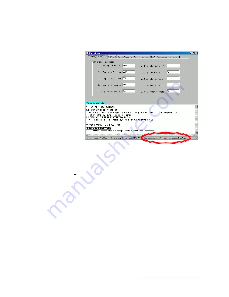
The currently open
configuration file is displayed
at the bottom of the D6200
window (see Figure 16).

To make a change to the
configuration of the D6600
you can access a
configuration file in one of
two ways:


If the D6200 Software
has read the
configuration files from
the D6600 before, then
there will be a saved
version of the file on the
hard drive of the
computer running the
D6200 Software. To
read the files into the
D6200 Software to allow
editing, select 

File

, then

select 

either Open CPU

Host and Network
Configuration

 or 

Open

Line Card
Configuration

.

Figure 16:  CPU Configuration Window

Then select the appropriate file to view or edit.


If the configuration files have never been read from the D6600 (new installation) then a generic version of
the files are located on the hard drive of the computer running the D6200 Software. (These generic files
were copied to the hard drive at the time of the D6200 installation.) To read the files into the D6200 software
to allow editing, select 

File

, then select either 

Open CPU Host and Network Configuration

 or 

Open Line

Card Configuration

. Then select the appropriate file to view or edit. For the CPU Host and Network

configuration file the generic file is named “default.cpu”. For the Line Card configuration file the generic file is
named “default.lnc”

Summary of Contents for D6600 NetCom

Page 1: ...D6600 NetCom Network Communications System System Guide ...

Page 2: ...m D6600 NetCom System Guide 46542C Page 2 2001 Radionics Trademarks Microsoft Windows Windows NT are either registered trademarks or trademarks of Microsoft Corporation in the United States and or other countries ...

Page 3: ... D6200 Programming Software Overview 31 4 1 D6200 Software Password Protection 31 4 2 Upgrading the Firmware Files in the D6600 via the D6200 Software 32 4 2 1 Finding the Firmware version number 32 4 2 2 Firmware Files Upgrade Procedure 33 4 3 D6200 Program Access Rights Restricting Access for Low Level Users 37 4 4 D6200 User Management Adding Authorized Administrator Users 37 4 4 1 Adding a Use...

Page 4: ...EXE 55 5 7 Verification that the IP Address Assigned is Correct 56 5 8 Using Telnet to Finish the Configuration 57 5 9 Status LEDs 60 5 10 9000 Series Panel Programming for Communication 60 6 0 RAM IV NetCom Programming 61 6 1 RAM IV And D5200 Programmer Handler Requirements 61 6 1 1 SDI Automation 61 Enable SDI Auto 61 Baud Rate 61 Parity Stop 61 9133 Supervision 62 RTS Control 62 DTR Control 62 ...

Page 5: ...hes 73 7 7 LEDs 75 7 7 1 Dialer LED 75 7 7 2 Status LED 75 7 8 Factory Programmed Default IP Address 75 7 9 Identifying the MAC Hardware Address 76 7 10 Obtaining an IP Address 76 7 11 Initial Assignment of the IP Address using ARP EXE 76 7 12 Verification that the IP Address Assigned is Correct 77 7 13 Using Telnet to Finish the Configuration 78 8 0 Tools for Radionics D6600 NetCom Diagnostics 83...

Page 6: ...Address Label 54 Figure 20 arp g table 56 Figure 21 Telnet Session 58 Figure 22 Telnet session Gateway Address 59 Figure 23 9000 Series panel 60 Figure 24 RAM IP Address Prompts 64 Figure 25 Path IP Add1 to Add4 66 Figure 26 Poll Rate Timeline 67 Figure 27 Phone parameters 70 Figure 28 Routing parameters 70 Figure 29 Enhanced Routing parameters 70 Figure 30 Enhanced Communications and Route Group ...

Page 7: ...Connections 53 Table 17 D9133TTL E Default IP Addresses 54 Table 18 Netmask Address 59 Table 19 D9133TTL E Status LEDs 60 Table 20 C900TTL X Dialer Format Settings Dipswitches 1 4 74 Table 21 C900TTL X Dipswitches 5 10 74 Table 22 C900TTL X Dialer LED Status Description 75 Table 23 C900TTL X Status LED Status Description 75 Table 24 C900TTL X Default IP Addresses 75 Table 25 Netmask Address 80 ...

Page 8: ...D6600 NetCom Contents D6600 NetCom System Guide 46542C Page 8 2001 Radionics Notes ...

Page 9: ...rface 6 RAM IV NetCom Programming provides Handler requirements for both RAM IV and the D5200 plus information on the programming prompts encountered in the RADXAUX1 Handler 7 C900TTL X Configuration provides configuration programming and assigning of IP address assignment instructions for the C900TTL Dialer Capture Modules 8 Tools for Radionics D6600 NetCom Diagnostics provides explanation of uti...

Page 10: ...ed to indicate to the user that a specific key should be pressed Example type F1 and press Italicized Text Text that appears like this indicates what would be seen in the D5200 Programmer s Display It is used as a section heading and screen example Shaded boxes indicate programmer prompts that are only available when Custom or View Events are selected Used only in the Program Entry Guide documents...

Page 11: ...equires a separate Radionics D6680 Network Adapter for each COM port to be used in order to interface with either a Token Ring or Ethernet network Most applications will not initially require that both COM ports be used The Radionics D6680 Network Adapters are specific to the type of network and application to which you will be connecting Table 3 Network Adapters Part Numbers All Alarm Panels to b...

Page 12: ...ming Administrative Software Ethernet NIC Figure 2 D6600 NetCom System Connection Diagram using C900TTL any Alarm Panel The figure at the right is a diagram of a D6600 NetCom System using Radionics 9000 Series panels D9133TTL E Serial Interface D6600 Receiver and D6680 Network Adapters The Radionics D6200 Programming Administration Software is a D6600 programming utility that is designed to work o...

Page 13: ...twork MUST use Token Ring cables The D6200 host computer MUST have a properly configured Token Ring network interface card NIC installed The D6600 Receiver Gateway MUST be connected to the Token Ring network via a Radionics D6680 T Network Adapter If connecting the D6680 Network Adapter s CHANNEL 1 port to COM4 COM1 on the D6600 use a straight modem cable 9 pin female to 25 pin male If connecting ...

Page 14: ...Plug the AC Power Cord into the rear of the D6600 Plug the other end into an unswitched 120 VAC 60 Hz or 220 VAC 50 Hz line Keep the power off to the receiver OFF ON 1 2 3 4 Detection Systems Inc Fairport N Y USA Input 85 264 AC 47 63 Hz 2 5 Amps B A T T E R Y D6645 Line Terminator Card D6615 CPU Terminator Card External Parallel Printer Connection 25 pin D6672 COM1 Expansion Kit Figure 5 D6600 Re...

Page 15: ...lled See the D6672 Installation Sheet for details COM1 is the 9 pin connector to the left of the CPU Terminator card looking at the rear of the unit Use a straight modem cable if connecting to Channel 1 the 25 pin connector of the D6680 Network Adapter Use a NULL modem cable if connecting to Channel 2 the 9 pin connector of the D6680 Network Adapter See Figure 6 or Figure 7 for pin outs 11 If you ...

Page 16: ...display will then show 05 22 2000 00 15 05 26 The D6600 unit is now close to being ready to accept signals from digital dialers via the phone line ALTHOUGH THE D6600 IS CLOSE TO RECEIVING SIGNALS VIA THE TRADITIONAL PHONELINE OTHER D6600 PROGRAMMING STEPS MUST BE PERFORMED BEFORE THE D6600 CAN COMMUNICATE TO THE NETWORK VIA THE NEWLY INSTALLED D6680 Network Adapter THIS PROGRAMMING CAN BE PERFORME...

Page 17: ...nect the other end of the COM1 connector cable to the 4 pin connector at the front bottom corner of the CPU Card The cable should be connected with the red wire on the top and the connector tabs facing toward the inside of the receiver 7 Once the installation is complete the rear of the receiver should resemble Figure 5 8 To connect COM1 to the network please refer to the previous Section 2 2 D660...

Page 18: ...ter an IP address and subnet mask for the network you will be setting up such as 202 96 168 1 Note If you have any questions regarding the assignment of the IP address or subnet mask see the network administrator All devices that will be using this network will usually have the same first three digits of the 4 digit IP address For example all IP addresses would be 202 96 168 xxx where xxx is diffe...

Page 19: ...ONTINUE ON WITH THE FOLLOWING STEPS These steps are ONLY necessary if the host computer running the D6200 Software is connected to the D6600 s COM4 port via a direct NULL modem serial cable 9 In Microsoft Windows operating system click on the Start button and then go to Settings and Control Panel 10 Once the control panel is open find and double click on the System icon to launch the System contro...

Page 20: ...der the part number D6600 CD XXXX XXXX is the current revision number The D6200 Software comes on the installation CD equipped to administer up to 10 client accounts To administer more than 10 client accounts an external Security Key must be installed on the host computer A Security Key is a device that attaches to a computer to control access to a particular application or features of an applicat...

Page 21: ...oper setup per the previous steps it is time to program the IP address of the D6680 Network Adapter The first step is finding and writing down the MAC or hardware address of the D6680 Network Adapter MAC is short for Media Access Control address a hardware address that uniquely identifies each node of a network This address is hard coded into the D6680 Network Adapter during its manufacture and ca...

Page 22: ...se the ARP program to assign the D6680 Network Adapter its new IP address ARP short for Address Resolution Protocol is a program used to convert an IP address into a hardware address such as a MAC The ARP program is installed into the C WINDOWS directory by default by Microsoft Windows 95 Windows 98 Windows 2000 and Windows NT during install At the MS DOS prompt usually C WINDOWS the following com...

Page 23: ... verify that the IP address is assigned to the D6680 Network Adapter and is recognized by the network At the DOS prompt type arp g ENTER 2 Figure 12 shows the Internet address IP ADDRESS and the corresponding Physical Address MAC hardware address The first line of the arp table above shows that the network recognizes the D6680 Network Adapter with a MAC address of 00 20 04a 12 04 0e and has tempor...

Page 24: ...indow will appear 5 Type the IP address of the D6680 Network Adapter into the Host Name field this is the IP address that was assigned to the D6680 Network Adapter in the previous section Enter 1 into the Port field and leave the TermType field at vt100 REMEMBER THAT THE IP AND MAC ADDRESSES USED IN THIS EXAMPLE WILL NOT BE THE SAME AS THE NUMBERS YOU ARE USING THIS IS FOR DEMONSTRATION ONLY 6 Cli...

Page 25: ... address in the past it will be displayed in parentheses For example if this D6680 Network Adapter were originally programmed to IP address 190 200 128 152 we would be changing it to address 190 200 128 220 11 To properly program the IP address 190 200 128 220 the following keys would be entered 190 ENTER 200 ENTER 128 ENTER 220 ENTER Note REMEMBER THAT THE IP ADDRESS USED IN THIS EXAMPLE WILL NOT...

Page 26: ... you do do not lose the password Otherwise you will not be able to re enter a TELNET programming session with the D6680 The unit will have to be sent back to the factory and reconditioned before it will be able to receive another TELNET session 15 Now press 1 ENTER to go into setup Channel 1 configuration The following will be displayed You must set the baud rate of the D6680 to 38400 Enter 38400 ...

Page 27: ...y if this is a new D9133TTL that has never been programmed before If your unit has been programmed before you will automatically arrive at the save changes and exit function next step Table 9 New D9133TTL E Parameters 21 Press 9 ENTER to save changes and exit the TELNET session A message is displayed that the connection was lost Click OK and close the TELNET window Configuration of the D6680 Netwo...

Page 28: ...e using a D6680 Network Adapter on a network Note For this to function a properly configured D6680 Network Adapter must be installed per the previous sections If they are not installed then further D6200 software programming via the network is not possible 1 Enter programming mode from the front panel keypad of the D6600 by pressing M E M E Note To change any programming parameter follow this synt...

Page 29: ...not set to 1 press M E then enter 1 then M E 13 Press CAN multiple times to return to the idle stage time and date on the LCD 3 9 Editing Program Parameters The D6600 must have account database information entered into it before it can be ready to manage and receive signals from alarm panels connected to D9133TTLs or C900TTLs Radionics recommends programming this information using the D6200 Progra...

Page 30: ...D6600 NetCom Configuration of the D6680 Network Adapter s D6600 NetCom System Guide 46542C Page 30 2001 Radionics Notes ...

Page 31: ...ree files can be modified uploaded or downloaded separately Be sure to review the previous Section 2 2 D6600 Receiver Gateway NetCom Installation before connecting or using the D6200 See Section 4 7 Opening Editing D6600 Configuration Files on Host PC for details on working with these files 4 1 D6200 Software Password Protection The D6200 Programming Administration Software is password protected T...

Page 32: ...ck the software versions loaded in the receiver Use of the 6200 Programming Software Through the keypad on the receiver Through D6200 Programming Software 1 Click on User Interface menu and select Software Version 2 This will display the CPU and Line Card software versions on your PC Through the D6600 keypad You will see this screen on the D6600 1 Press M E and enter the password The default passw...

Page 33: ...ontents of the CD use Microsoft Windows Explorer or Microsoft Windows NT Explorer in an NT environment To access Windows Explorer go to Start à à Programs à à Windows Explorer 2 Insert the D6600 CD into your CD ROM drive It contains the files necessary to perform the upgrade Use Windows Explorer to navigate over to the CD ROM drive then open the D6200 Programmer folder Open the Firmware subfolder ...

Page 34: ...is being performed 6 Once the extraction of the CPU software file is complete the window will disappear Loading the D6600 CPU software from the CD to your computer is now complete 7 You must now launch the D6200 Software It will be used to load the newly extracted software into the D6600 After the program initiates click on the Programming and select Software Upgrade Wizard 8 A window will then be...

Page 35: ... should change to an open folder 14 Look to the right hand side window You should see a System Files firmware file 15 Double click the System Files software file A window should then open that tells you that by clicking the OK button the software will be installed on your computer Click OK A window will then briefly display identifying that the extraction process is being performed Once the extrac...

Page 36: ...at the extraction process is being performed Once the extraction of the PSTN software file is complete the window will disappear Loading the D6600 PSTN software from the CD to your computer is now complete 21 Click on the Programming menu and select Software Upgrade Wizard The Upgrade wizard window will appear 22 The program must then be told which software files you would like to send to the D660...

Page 37: ...elective access to administration of the D6600 database However you may choose to restrict that access to certain areas When adding or editing users from the User Management window access rights are chosen from one of four categories All All except User Management Read Off Line Modification User Defined If no access rights are designated the user access rights default to Read Off Line Modification...

Page 38: ...ges will be automatically saved 4 4 2 Editing an Existing User To edit a user name password or access rights follow the steps below 1 Click on the appropriate cell to edit a user name password or access rights Click Modify allowing the user to modify the current value 2 Make the appropriate changes then click OK 3 Click Close and the changes will be automatically saved 4 4 3 Deleting an Existing U...

Page 39: ...en installed click the Restore button in the new D6200 Software and the previously setup user configurations will now be loaded into the new D6200 4 6 Changing User Password The currently logged in user can change his her password at anytime To do so follow the steps below 1 Click on the Settings menu and select Change Password 2 A Password Check window will appear Enter the User ID and Password N...

Page 40: ...of the computer running the D6200 Software To read the files into the D6200 Software to allow editing select File then select either Open CPU Host and Network Configuration or Open Line Card Configuration Figure 16 CPU Configuration Window Then select the appropriate file to view or edit If the configuration files have never been read from the D6600 new installation then a generic version of the f...

Page 41: ...uration from D6600 A communication status window appears 2 Click OK to close the status window once file transfer is complete The D6600 s CPU Host Network and Line Card configuration files are now located in the D6200 Program Keep in mind that these files now reside in RAM memory and are available for editing However if any changes are made you must save a copy to the hard drive for archival purpo...

Page 42: ...D6200 using either one of the methods described above the user can now view and edit all of the parameters 1 Click on the User Interface menu from the D6200 Menu Bar and select the CPU Configuration 2 Select configuration file to be viewed or edited Click the tabs of the program selections you wish to view or modify and enter values Value changes will be saved temporarily when the window is closed...

Page 43: ...comports or network connections Through the D6200 software the user can view the status of all accounts in the database add accounts edit accounts delete accounts and configure network operations Note Connect D6200 software to the network through the COM4 or COM1 port of the D6600 All account database configurations will be lost when the D6600 is rebooted Be sure to save all database configuration...

Page 44: ...abase in the D6200 1 Select NetCom menu then Account Database Configuration An Account Database window will appear 2 The Account Database file shows all of the networked field accounts programmed into the D6600 From here you can add delete or edit any of the accounts A Search functions see Table 12 and Section 4 12 1 Searching the Account Database B Account Operations see Table 13 A B C C See Tabl...

Page 45: ...2 Enable Allows searching by disabled 0 or enabled 1 Panel poll rate Allows searching by specific poll rates see Poll Rate in Table 14 Table 12 Account Database Configuration Search Options Buttons Name Description Add Account Adds a new account to the database See Section 4 11 3 Adding an Account in the Database Copy Account Makes a copy of an existing account See Section 4 11 5 Copying Account I...

Page 46: ... the receiver Selection Seconds 0 0 1 30 2 60 3 90 Poll Rate This is a range of zero to 300 seconds in 30 second intervals Enter the value that is closest to the number of seconds desired for polling the receivers 4 120 Status The current communication status between the panel and D6600 0 panel is OFFLINE 1 panel is ONLINE Status Changed Time The time and the date status of the IP address were cha...

Page 47: ...r is used to identify which panel has lost its network connection when an Off Normal Status message appears If no Virtual Account number has been entered the default message ACT0000 Off Normal Status message appears In this case the only way to identify which panel has lost its network connection is to read through the D6200 and view the status of the panels in the account database Enable Communic...

Page 48: ...etCom menu and select Account Database Configuration The Account Database Configuration window will appear 2 The Account Database file shows all of the networked field accounts programmed into the D6600 See Table 14 Account Database Column Definitions for a description of each column in the table The same screens that you used to add an account are used here The only difference will be that the fi...

Page 49: ... Click OK and the new account should appear in the database This tool is extremely useful when account information is the same for several different panels 4 11 6 Deleting an Account from the Database 1 Click on the NetCom menu then select Account Database Configuration 2 Highlight the appropriate account and then click Delete 3 A window will pop up to confirm the deletion Click Yes or No 4 Click ...

Page 50: ...ect Account Database Configuration Click on the desired heading by which the program should sort the database The user can choose to sort the database by IP address Virtual Account Virtual Line Enable Poll Rate Status or Status Changed Time 4 12 3 Status Under Account Database Configuration this value will be either be a 1 or a 0 A 1 will indicate that the connection is good between the receiver a...

Page 51: ...tton In this window under the Account tab select the device in the Net Device section then click OK NOTE If this is left blank no selection the account will be displayed in the selection window In the C900 Command window select the C900 account that will receive the commands Select the command that will be transmitted to the C900 See definitions above Click the change button this message will be t...

Page 52: ...t Supervision Rate Changed in the D6600 Computer Interface Manual P N 39963F or later for the D6600 output format 4 13 1 7 Active C900 Acknowledgement from Dialer This command specifies the time in seconds for the C900 to receive the acknowledgment or other information from the dialer The C900 will enter the Active mode if it does not receive the dialer acknowledgement from the receiver Valid entr...

Page 53: ...s Control Communicator D9133TTL E PERIPHERAL DEVICE WIRING RED YELLOW GREEN BLACK POWER DATA BUS A COMMON DATA BUS B 31 30 32 29 Control Communicator 9000 Series Control Communicator D9133TTL E SDI PWR Terminal 32 SDI PWR SDI A Terminal 31 SDI A SDI B Terminal 30 SDI B SDI COM Terminal 29 SDI COM 2 Wire the D9133TTL E to the Control Communicator as indicated in Table 16 D9133TTL E Wiring Connectio...

Page 54: ...33TTL E Serial Interface s default IP addresses Table 17 D9133TTL E Default IP Addresses 5 4 Identifying the MAC Hardware Address Note If you already know the IP address of the D9133TTL E and it has already been configured see Section 5 7 Verification that the IP Address Assigned is Correct Once everything is verified and set up properly per the steps in Section 5 2 Physical Installation it is tim...

Page 55: ...rk that is to be used You will now need to use the ARP program to assign the D9133TTL E its new IP address At the DOS prompt usually C windows the following command syntax is to be used arp s xxx xxx xxx xxx zz zz zz zz zz zz xxx xxx xxx xxx is the IP address assigned to the D9133TTL E Serial Interface by the Network Administrator zz zz zz zz zz zz is the MAC hardware address found on the label of...

Page 56: ...ecessary to verify that the IP address is assigned to the D9133TTL E and is recognized by the network At the DOS prompt type arp g ENTER Figure 20 arp g table shows the Internet address IP ADDRESS and the corresponding Physical Address MAC hardware address The first line of the table above shows that the network recognizes the D9133TTL E with a MAC address of 00 20 4a 12 04 0e and has temporarily ...

Page 57: ...3 Click on the Connect menu and select Remote System 4 The Connect window will appear 5 Type the IP address of the D9133TTL X into the Host Name field this is the IP address that was assigned to the D9133TTL X in the previous section Enter 1 into the Port field and leave the TermType field at vt100 6 Click Connect and wait a few seconds for a message to display saying Connect Failed Could not open...

Page 58: ...e 21 Telnet Session 10 Press 0 ENTER to set up the basic Server Configuration You are now required to enter the desired IP address If the D9133TTL E Network Interface module has been programmed with an IP address in the past it will be displayed in parentheses as shown to the right For example this D9133TTL E was originally programmed to IP address 190 200 128 152 We are now changing it to address...

Page 59: ...prompted to change the Telnet password press N for the default of No This screen will now show the Setup Mode screen you saw previously Be careful NOT to enter a password into the D9133TTL X by accident or select Y to change the password If you do do not lose the password Otherwise you will not be able to re enter a TELNET programming session with the D9133TTL X The unit will have to be sent back ...

Page 60: ...m the Ethernet NETWORK SER TX Flashes when data is transmitted to the Ethernet NETWORK from the D9133TTL E Table 19 D9133TTL E Status LEDs 5 10 9000 Series Panel Programming for Communication The RADXAUX1 Handler is a new handler for the 9000 Series panels and is primarily used for programming Enhanced Communication capabilities such as NetCom As new features that require new programmable prompts ...

Page 61: ...erface module that allows the 9000 Series panels version 6 00 and higher to send receive information to from an external software program This Automation protocol will allow external software programs perform functions such as arming and disarming areas changing user passcodes and names and turning relays on and off to name a few The following items allow some simple configuration options however ...

Page 62: ...the D9133 Pressing the SPACE bar on the D5200 toggles through the available options On THIS IS THE SETTING NECESSARY FOR NetCom NETWORK COMMUNICATIONS AutoD Sets this to Auto DTR Off Sets DTR off hardware control Status Rate Default 0 Selections 0 255 This item determines how often the default status information is sent to the D9133 Serial Interface Module The Status information includes the curre...

Page 63: ...cations over the SDI bus This item must be set to Yes if you plan on using the External Modem configuration a private Local or Wide Area Network or local RAM IV programming Yes Enable RAM sessions over the SDI bus If set to YES the RAM Line Monitor is always ready No Do not enable RAM sessions over the SDI bus Note If the reset pin is in the locked position local RAM IV programming is still allowe...

Page 64: ...RAM IP Address 2 Default 0 Selections 0 255 See RAM IP Address 1 RAM IP Address 3 Default 0 Selections 0 255 See RAM IP Address 1 RAM IP Address 4 Default 0 Selections 0 255 See RAM IP Address 1 Enable Ext Modem Default No Selections Yes or No Setting this item to Yes instructs the 9000 Series Control Communicator that SDI Address 88 is enabled for use with an External Modem For further informatio...

Page 65: ... External Modem when the panel is powered up Programming Note 0101 0101 0101 This item can only be programmed successfully from RAM IV The D5200 Programmer does not allow certain characters as noted above RAM Dial String Default ATDT Selections Not yet implemented This item is not yet implemented 6 1 3 Enhanced Communications Enhanced Communications is the ability to communicate by some other mean...

Page 66: ... paths available when using the D5200 An IP Address consists of four fields Each field has a range of 0 255 As an example an IP Address is expressed as 110 227 64 190 The D5200 Programmer has split the IP Address into four programmable fields Be sure you contact your network administrator to find out exactly which IP Address events are to be sent to 110 227 64 190 Path IP Add1 Path IP Add2 Path IP...

Page 67: ... Path 1 is generated and sent to the central station To show how the Retry Count operates we will assume that the acknowledgement is not received in 10 seconds When this occurs the heartbeat event is re sent after the first 10 second ack wait period has expired If this heartbeat event is not acknowledged the panel declares this Path as failed and generates the Comm Fail SDI Event but continues to ...

Page 68: ...her Instead offset these values by 2 or 3 For example if your Path Ack Wait time 15 program your Time Out value as 17 in the RAM IV account Path Retry Count Default 5 Selections 0 255 This item determines how many times the panel will re send the heartbeat event before declaring a Path Failure and generating a COMM FAIL RG SDI RG 1 4 SDI 88 for Path 1 89 for Path 2 90 for Path 3 91 for Path 4 even...

Page 69: ...On Selections On AutoD Off This item determines how the Data Terminal Ready Control parameters are defined for the D9133TTL E or D9133TTL TR Pressing the SPACE bar on the D5200 toggles through the available options On THIS IS THE SETTING NECESSARY FOR NETWORK COMMUNICATIONS AutoD Sets this to Auto DTR Off Sets DTR off hardware control 9133 Supervision Default No Selections Yes or No This item dete...

Page 70: ...lication with the 9000 Series panels may be to use NetCom as the Primary Path in a given Route Group and then use a standard PSTN phone line as the Backup Path In this configuration if an event is unable to reach the central station after one or two attempts the system will then attempt to send the original event using the Backup Path over the phone line as well as a Comm Fail SDI event which indi...

Page 71: ... via a Telco cord The third marked ETHERNET is for connection to the Ethernet NETWORK RG 45 interface In Intercept Mode the C900TTL X connects the house phone directly to the telephone company and connects the digital dialer to its internal Telco simulation electronics In Fallback Mode the C900TTL X connects the house phone to the Alarm Panel and the Alarm Panel to the telephone company shunting i...

Page 72: ...etainer tabs the circuit board will rest on the two support posts 3 Secure the bottom of the enclosure by screwing the bottom two holes through the support posts and through to the control retainer holes Once the circuit board is installed be sure to connect its ground wire to the top hinge of the panel enclosure 7 3 Overview of Onboard Inputs The C900TTL X has 3 inputs monitored by A D converters...

Page 73: ...ns of the C900TTL s Power Terminal Strip 12 V Connect regulated 12 volt DC power to this terminal and the 12 V terminal This power may be supplied by a separate power supply battery or Auxiliary power from the Control Communicator 12 V Return terminal for the 12 VDC power supply earth ground connection 10K EOL Resistor Figure 34 C900TTL X Onboard Terminal Strip 7 6 Setting the Dipswitches A 10 pos...

Page 74: ... information The switch positions will be referred to as DS 5 for Dipswitch 5 etc Switch and Condition APPLICATION DS 5 ON Enable AUTO FALLBACK condition after detection of an intercept error DS 5 OFF Disable AUTO FALLBACK condition after detection of an intercept error DS 6 ON No number of hang ups will cause FALLBACK MODE DS 6 OFF Third hang up without D6600 or host computer ACK causes error DS ...

Page 75: ...d Blinking 5 hertz Green The host is responding normally Red The host is not responding Blinking repeating code Red A Self Test error has occurred The code is a series of rapid blinks repeated every second 1 blink ROM checksum error 2 blinks RAM test error Steady Red Green Off The C900 has crashed or has no power The STATUS LED indicates the status of the host interface and of the C900 itself Hert...

Page 76: ...re step before beginning Also make sure there is power to the C900TTL X and the Ethernet Network RJ45 connection is in place The C900TTL X being configured and the PC being used to configure it must both be on the same gateway the device that connects the LAN to the WAN In order to Telnet the process of using the TELNET program to communicate with the C900TTL X and establish it s communications co...

Page 77: ...Address that was just assigned is correct follow the steps below REMEMBER THAT THE IP AND MAC ADDRESS USED IN THIS EXAMPLE WILL NOT BE THE SAME AS THE NUMBERS YOU ARE USING THIS IS FOR DEMONSTRATION ONLY It is now necessary to verify that the IP address is assigned to the C900TTL X and is recognized by the network At the MS DOS prompt type arp g ENTER Figure 37 shows the Internet address IP ADDRES...

Page 78: ...the MS DOS prompt usually C WINDOWS type telnet ENTER The telnet application should now be running 3 Click on the Connect pull down menu and then Remote System The Connect window will appear 4 Type the IP address of the C900TTL X Dialer Capture Module this is the IP address that was assigned to the C900TTL X Dialer Capture Module in the previous section into the Host Name field Enter 1 into the Po...

Page 79: ...ds then you should see the following screen See Figure 38 Figure 38 Telnet Session 9 Press 0 ENTER to set up the basic Server Configuration You are now required to enter the desired IP address If the C900TTL X Dialer Capture Module has been programmed with an IP address in the past it will be displayed in parentheses as shown to the right For example if this D6680 Network Adapter was originally pr...

Page 80: ...92 16 255 255 0 0 26 252 0 0 0 7 255 255 255 128 17 255 254 0 0 27 248 0 0 0 8 255 255 255 0 18 255 252 0 0 28 240 0 0 0 9 255 255 254 0 19 255 248 0 0 29 224 0 0 0 10 255 255 252 0 20 255 240 0 0 30 192 0 0 0 31 128 0 0 0 Table 25 Netmask Address 13 You will be prompted to change the Telnet password press N for the default of No This screen will now show the Setup Mode screen Be careful NOT to en...

Page 81: ...s in the form of 000 000 000 000 ENTER to change it 21 You should then see Press ENTER to accept the default of 07700 If it doesn t show that type 07700 ENTER to change it 22 You should then see Press ENTER to accept the default of 00 If it doesn t show that type 00 ENTER to change it 23 You should then see Press ENTER to accept the default of 00 If it doesn t show that type 00 ENTER to change it ...

Page 82: ...D6600 NetCom C900TTL X Configuration D6600 NetCom System Guide 46542C Page 82 2001 Radionics Notes ...

Page 83: ... to verify Write down the IP address 2 Open a MS DOS window by selecting Start à à Programs à à MS DOS Prompt A MS DOS window will appear 3 Use the PING command followed by the IP address of the device you are attempting to verify The correct syntax is ping xxx xxx xxx xxx ENTER xxx xxx xxx xxx is the IP address assigned to the D9133TTL E or C900TTL E by the network administrator 4 For example to ...

Page 84: ...D6600 NetCom Tools for Radionics D6600 NetCom Diagnostics D6600 NetCom System Guide 46542C Page 84 2001 Radionics Notes ...

Page 85: ...ct serial connection between the D6600 and the Automation System This is true serial cable emulation over the network see Figure 42 Direct Serial LAN Connection Configuration D6600 Receiver D6680 1 D6680 2 Automation System 192 158 001 017 192 168 001 016 COM3 Ethernet RS232 Figure 42 Direct Serial LAN Connection Configuration The commands necessary for this configuration to automatically establis...

Page 86: ...D6600 NetCom Special Radionics D6600 NetCom Applications D6600 NetCom System Guide 46542C Page 86 2001 Radionics Notes ...

Page 87: ...m Guide 2001 Radionics Page 87 46542C 10 0 UL Compliance Installation To correctly install the NetCom system according to UL Standards please refer to the following document D9133TTL E Installation Guide P N 41124 C900TTL E Installation Instructions P N 41123 ...

Page 88: ...D6600 NetCom UL Compliance Installation D6600 NetCom System Guide 46542C Page 88 2001 Radionics Notes ...

Page 89: ... Configuration 71 Answer Armed SDI RAM Parameters 64 Answer Disarmed SDI RAM Parameters 65 Applications Special NetCom 85 Direct Serial Connection Emulation 85 Assignment using ARP IP Address C900TTL X 76 D6680 22 D9133TTL E 55 B Baud Rate SDI Automation 61 SDI RAM Enhanced Communication 68 BUS RX Status LEDs D9133TTL E 60 BUS TX Status LEDs D9133TTL E 60 C C900 Commands Changing Status Activate O...

Page 90: ...71 Default IP Address 75 Identifying MAC Hardware Address 76 IP Address Assignment using ARP 76 IP Address Finishing configuration using TELNET 78 IP Address Verification 77 Network Enabling Alarm panel 71 Obtaining an IP Address 76 Physical Installation 72 LEDs 75 Dialer 75 Status 75 Onboard Inputs 72 Onboard Outputs 73 Onboard Terminal Strip 73 Setting Dipswitches 73 D6680 21 D6600 Programming 2...

Page 91: ...ing 42 D6600 Configuration Files Editing 42 Sending to D6600 43 Finding version number through 32 Software Installation 20 D6201 Security Key 20 multiple versions 20 D6600 Configuration Files Editing on Host PC 40 Editing using D6200 Software 42 Opening on Host PC 40 Reading on Host PC 41 Sending to 43 from D6200 PC 43 Viewing using D6200 Software 42 D6200 Software Configuration Files Editing 42 V...

Page 92: ...lation Guide 53 Status LEDs 60 Network Adapters Configuration IP Address Finishing configuration using TELNET 57 Operation Installation Guide 9 87 Configuration Physical Installation 53 Status LEDs BUS RX 60 BUS TX 60 ETHERNET LINK 60 SER RX 60 SER TX 60 D9133TTL TR 63 68 69 D9412 9 Database Reading First Time 43 Previous 43 Searching Account Status 50 Sorting Account Status 50 Status of Account S...

Page 93: ... Parameters 63 SDI RAM Enhanced Communications Configuration 68 Host PC D6600 Configuration Files Editing 40 Opening 40 Reading 41 Requirements Pre Installation 13 Setting Up 17 I Identifying MAC Hardware Address C900TTL X 76 D6680 21 D9133TTL E 54 Idle Changing Status 52 Important Note C900 must emulate a phone and line and a digital receiver 73 C900TTL X and PC must both be on same gateway to te...

Page 94: ...1 D9133TTL E 54 Manual Organization Introduction 9 Modem Init String SDI RAM Parameters 65 N NetCom Diagnostic Tools 83 IP Assignment Verification 83 Network Communications Verification 83 Host PC D6200 Software Installation 20 Installation 14 Optional Serial COM1 17 Overview 11 Programming D5200 Handler Requirements 61 RAM IV 61 Handler Requirements 61 Enhanced Communications 65 IP Address Progra...

Page 95: ...ation 61 SDI RAM Enhanced Communication 69 Password Protection D6200 Software 31 Path Ack Wait Programming Path s 68 Path IP Add1 Programming Path s 66 Path IP Add2 Programming Path s 66 Path IP Add3 Programming Path s 66 Path IP Add4 Programming Path s 66 Path Poll Rate Programming Path s 66 Path Programming Requirements Handler NetCom RAM IV Programming 66 Path Retry Count Programming Path s 68 ...

Page 96: ... Enable Ext Modem 64 Enable SDI RAM 63 Enhanced Comm 65 Modem Init String 65 RAM Dial String 65 RAM IP Address 1 64 RAM IP Address 2 64 RAM IP Address 3 64 RAM IP Address 4 64 RAM Line Monitor 65 Seize Relay 65 SDI RAM Enhanced Communication 9133 Supervision 69 Baud Rate 68 DTR Control 69 Parity Stop 69 RTS Control 69 R RADAUX1 Sections Configuration 61 Miscellaneous 61 Route Group Attempts 61 SDI...

Page 97: ...anced Comm 65 Modem Init String 65 RAM Dial String 65 RAM IP Address 1 64 RAM IP Address 2 64 RAM IP Address 3 64 RAM IP Address 4 64 RAM Line Monitor 65 Seize Relay 65 Requirements Handler NetCom RAM IV Programming 63 SDI RAM Enhanced Communication Prompts 9133 Supervision 69 Baud Rate 68 DTR Control 69 Parity Stop 69 RTS Control 69 SDI RAM Enhanced Communications Configuration Requirements Handl...

Page 98: ...Upgrade Procedure 33 Upgrading D6600 Firmware Files D6200 Software 32 Finding version number 32 Upgrade Procedure 33 User Management Add D6200 Software 38 Add User D6200 38 D6200 37 D6200 Software 37 Delete D6200 Software 38 Delete User D6200 38 Edit D6200 Software 38 Edit User D6200 38 Files Save D6200 Software 39 User Management Files Restore D6200 Software 39 User Password Changing D6200 39 V V...

Page 99: ...D6600 NetCom Notes D6600 NetCom System Guide 2001 Radionics Page 99 46542C ...

Page 100: ... 2001 Radionics a division of Detection Systems Inc PO Box 80012 Salinas CA 93912 0012 USA Customer Service 800 538 5807 46542C System Guide 5 01 D6600 NetCom Page 100 of 100 ...

Reviews: