D6600 NetCom
Communication System Overview
D6600 NetCom System Guide
46542C
Page 14
© 2001 Radionics
2.2
D6600 Receiver/Gateway NetCom Installation
Follow the steps below to correctly install the D6600 Receiver/Gateway.
1. Place the D6600
Receiver/
Gateway in a
secure location
(Rack mount,
Desktop, etc.)
2. Remove the tie
wrap from the
receiver door
handle. Open the
door and remove
the packaging
foam from the
front of the CPU
Card.
3. Verify CPU Card
and Line Card
connections by
gently pushing the
cards in their slots
until they are
securely
connected to the
CPU Terminator
Card and the Line
Terminator Card.
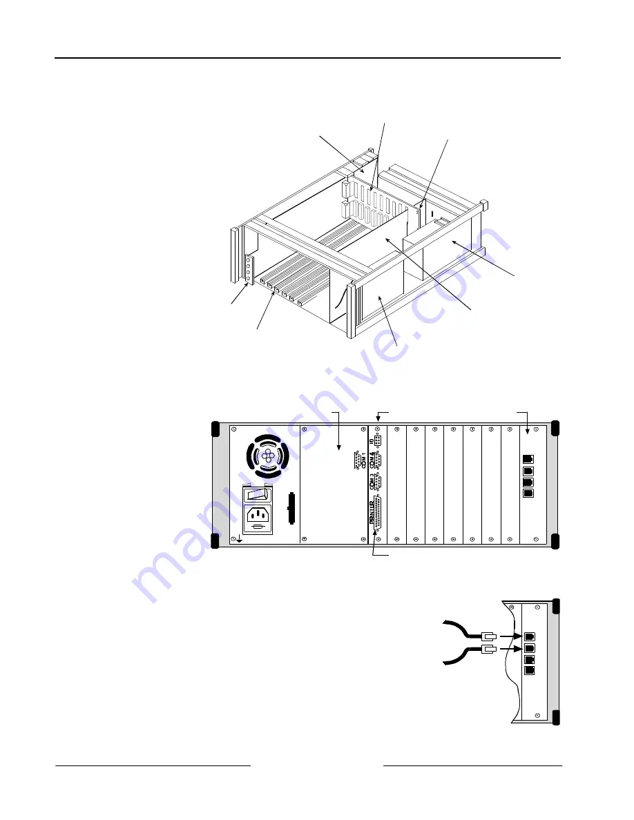
AC/DC POWER SUPPLY
(D6630)
CPU TERMINATOR CARD
(D6615)
BACKPLANE
TELEPHONE LINE CARD TERMINATORS
(D6645 or D6645INTL)
CPU CARD
(D6610)
DC/DC POWER SUPPLY
(D6631)
CARD GUIDES
TELEPHONE LINE CARD
(D6640)
Figure 4: D6600 Communications Receiver/Gateway Exploded View
4. Plug the AC Power
Cord into the rear of
the D6600. Plug the
other end into an
unswitched
120 VAC
60 Hz or 220 VAC
50 Hz line. Keep the
power off to the
receiver.
OFF
ON
1
2
3
4
Detection Systems Inc.
Fairport N.Y.
USA
Input:
85-264 AC
47-63 Hz
2.5 Amps
B
A
T
T
E
R
Y
D6645
Line Terminator Card
D6615
CPU Terminator Card
External Parallel
Printer Connection
(25-pin)
D6672 COM1
Expansion Kit
Figure 5: D6600 Rear Panel
5. Plug the telephone lines into the RJ-11 connectors on the Line
Terminator card (See Example 1).
6. Connect an External Parallel Printer (power off) to the 25-pin
connector, marked ‘PRINTER,’ on the CPU Terminator card.
7. Connect a D6680 Network Adapter (not included) to COM4, the top 9-
pin connector on the CPU Terminator card of the D6600 marked ‘COM
4.’ Use a straight modem cable if connecting to Channel 1 (the 25-pin
connector) of the D6680 Network Adapter. Use a NULL
modem cable
if connecting to Channel 2 (the 9-pin connector) of the D6680 Network
Adapter.
1
2
3
4
RJ-11 connector
of Line 1
RJ-11 connector
of Line 2
Example 1: Connecting phone
lines to D6600


