background image

9

Installation

4. Install all components, then connect all

related components. 

5. Connect the anemometer, outdoor

thermo/hygro sensor and rain gauge to
their individual solar transmitters to
receive the weather element data. Each
solar transmitter needs two AA batteries
(not supplied) for backup power. 

Notes: 

• Install the anemometer, outdoor thermo/

hygro sensor, and rain gauge outdoors
in a location that provides the best mea-
surement for the weather elements the
instruments are designed for.

• To reduce interference, do not install

individual solar transmitters closer than
3.28 feet (1 meter) to each other.

• We recommend that you use lithium bat-

teries in any component that could be
exposed to temperatures between –4°F
(–20° C) and –58°F (–50° C) or colder.

• If you are installing more than one

weather station in the same area, wait at
least 30 minutes between the installa-
tions.

Estimating the Mounting 
Distances

To help you find the right location for each
weather station component, follow the tips
listed in “Selecting a Location” on Page 11
that precede the mounting instructions for
that component.

Before you mount any of the components,
we recommend you select a general mount-
ing location for each component first, then
measure the distance between the locations
for components that you will be connecting to
each other to be sure the selected locations
are close enough together.

For the best reception, mount the solar trans-
mitters no more than about 328 ft (100 m)

from the monitor. Obstacles between the
solar transmitters and the monitor might
reduce the effective range.

The maximum length of serial cable (not sup-
plied) required to connect the monitor’s 

RS-

232

 jack to a PC is 10 feet, so the monitor

must be located indoors within 10 feet of
your PC.

CALIBRATING THE 
ANEMOMETER

Before you mount the anemometer at the
selected mounting location, follow these
steps to calibrate it with the monitor, so the
monitor properly measures wind speed and
direction.

Important: You must be able to view the
monitor while you assemble and calibrate the
anemometer. You must temporarily install
the monitor and connect AC power to it. Be
sure to follow these steps before you install
the anemometer at its mounting location. 

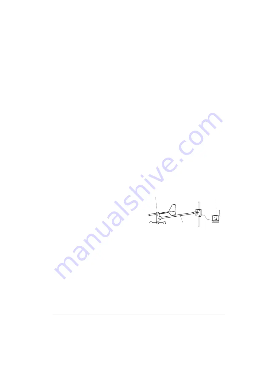
Assembling the Anemometer

1. Place the wind cup over the thin shaft on

the anemometer’s bar, use a small Phil-
lips screwdriver to tighten the screw on
the base of the wind cup, then insert one
of the supplied rubber screw covers into
the screw’s hole to protect the screw
from corrosion.

2. Use a Phillips screwdriver to loosen the

screws on the cover of the anemome-
ter’s solar transmitter, then remove the
cover. The anemometer’s cable and

Anemometer

Anemometer

Solar Transmitter

Bar

Summary of Contents for 63-1016

Page 1: ...Owner s Manual Please read before using this equipment Wireless Weather Station with Software...

Page 2: ...g the Weather Forecast Display 18 Using the Barometric Pressure Window 18 Using the Indoor Temperature Window 20 Using the Outdoor Temperature Window 21 Viewing and Resetting Max Min Relative Humidity...

Page 3: ...les with this equipment Features An attractive and useful addition to your home or business your RadioShack Wire less Weather Station uses 433 MHz radio signals to send and receive weather data betwee...

Page 4: ...when a set weather condition is reached Optional PC Connection lets you con nect the monitor to a personal computer using an optional serial cable so you can record and store weather data on your PC u...

Page 5: ...or liability what soever for any inconsistency inaccu racy or omissions for weather recorded reported or forecasted by the software the weather station or the Accu Data database or for reliance on su...

Page 6: ...Mounting Hardware Tools Additional Supplies Needed for Installation In addition to the supplied mounting hard ware you need the following tools and sup plies to install your weather station small fla...

Page 7: ...ibes each icon or control Icon Control Description Function barometric pressure absolute sea level Repeatedly press to toggle between the absolute and sea level baro metric pressure readings See Using...

Page 8: ...ach weather station component and carefully measure the approximate mounting dis tances 2 Make sure you have all the tools sup plies necessary to install each compo nent 3 Assemble and calibrate the a...

Page 9: ...locations for components that you will be connecting to each other to be sure the selected locations are close enough together For the best reception mount the solar trans mitters no more than about...

Page 10: ...or turn the shaft until appears next to 5 1 5 1 5 1 5 1 on the monitor This shows the wind direction Notes The current position of the shaft appears on the monitor about 14 sec onds after you turn the...

Page 11: ...Warning Be sure to follow all safety instructions provided with the mast 2 Using a compass for reference point the bar on which the anemometer is mounted so the end with the anemome ter and wind cup p...

Page 12: ...ge s cylinder off its base then carefully remove the packing tape from the bucket assembly 3 Replace the cylinder on the base align its screw holes then reinsert and tighten the screws Connecting the...

Page 13: ...as a metallic surface or a window with reflective coating near hot or cold sources such as a grill stove or clothes dryer vent or a heating or air conditioning unit in an area where it might get wet...

Page 14: ...temperature and humidity readings do not place the sensor where it will be outdoors in direct sunlight in water or in a location where it is likely to get wet on or close to a surface that easily abs...

Page 15: ...r can operate on fresh batter ies for up to 1 week without AC power The monitor might display inaccurate data if it is using backup battery power and battery power becomes low 1 Press the tab on the b...

Page 16: ...0 31 inches 8 mm 1 Drill two small pilot holes each shallow and slightly smaller in diameter than the screw 59 16 inches apart one beside the other at the desired mounting location 2 Thread a screw i...

Page 17: ...iew and the time with seconds view repeatedly press CLOCK Note If you selected the 12 hour format 0 0 0 0 appears during AM hours and 30 30 30 30 appears during PM hours USING THE DAILY ALARM You can...

Page 18: ...baro sensor USING THE BAROMETRIC PRESSURE WINDOW Setting Viewing the Barometric Display Units The weather station samples the barometric pressure every 15 minutes You can set it to display the current...

Page 19: ...the barometric pressure changes and meets the set condition 50 50 50 50 flashes and the monitor sounds an alarm for about 1 minute To silence the alarm sooner press any key Note If you press a key to...

Page 20: ...s in memory and record a new maximum or minimum temperature beginning with the current reading hold down MEMORY for about 2 seconds Using the HI LOW Temperature Alarms You can set the monitor to sound...

Page 21: ...50 50 50 50 appears 3 Hold down SET until the indoor dew point setting flashes 4 Repeatedly press or hold down or to set the dew point alarm condition 5 Press SET to store the setting Note If you do n...

Page 22: ...287 287 287 appears 2 Repeatedly press ALARM so either or 2 2 2 2 appears 3 Hold down SET until the last tempera ture alarm condition flashes 4 Repeatedly press or hold down or to set the temperature...

Page 23: ...n press so appears VIEWING AND RESETTING MAX MIN RELATIVE HUMIDITY RECORDS The weather station samples the indoor and outdoor humidity and determines the relative humidity percentage The current indoo...

Page 24: ...desired RH or CHAN NEL if necessary Repeatedly press ALARM until the desired alarm setting 50 50 50 50 or 2 2 2 2 50 50 50 50 appears then repeatedly press until appears USING THE RAIN GAUGE The weath...

Page 25: ...condition display To continue programming the alarm condition start over at Step 2 1 Press RAIN 2 Repeatedly press ALARM until 50 50 50 50 appears 3 Hold down SET for about 2 seconds until the monito...

Page 26: ...the alarm stops sounding but continues to flash until the alarm condition is no longer met To view the current high wind speed alarm condition press WIND then press ALARM appears Note When no wind spe...

Page 27: ...once it receives the signal at a rate of 9600 bps For instructions on using the supplied software or viewing data sent from your monitor see the software s separate Owner s Manual SCANNING THE MONITOR...

Page 28: ...air must be cooled at constant pressure and constant water vapor content for saturation to occur When the dew point falls below freezing it is called the frost point downburst a severe localized downd...

Page 29: ...cles dispersed through a portion of the atmo sphere Individually these are not visible but cumulatively they diminish visibility heat index HI an index that combines air temperature and relative humid...

Page 30: ...e atmospheric pres sure at mean sea level severe thunderstorms intense thunder storms capable of producing heavy showers flash floods hail strong and gusty surface winds and tornadoes shower intermitt...

Page 31: ...has actually been observed either visually or on a radar screen tornado watch a forecast issued to alert the public that tornadoes may develop within a specified area trace of precipitation an amount...

Page 32: ...n Chart Clouds can float from a few feet above the earth fog all the way up to 40 000 feet and higher There are 11 different classes of clouds As the following chart illustrates you can distinguish cl...

Page 33: ...monitor s display locks up or the moni tor does not work properly or is receiving interference use a pointed object such as a straightened paper clip to press and release the RESET hole inside the mon...

Page 34: ...8 F 9 C Resolution Indoor and Outdoor 2 F 1 C Sampling Cycle Frequency Indoor 38 Seconds Outdoor 37 Seconds Wind Speed Operating Measurement 0 125 3 mph 0 56 m s Measurement Accuracy Range 2 10 m s 32...

Page 35: ...98 mm hr 7 1 unit Daily and Cumulative Resolution 04 in 1 mm Rainfall Rate Resolution 04 in hr 1 mm hr Daily Sampling Cycle Frequency 24 Hours Rainfall Rate Sampling Cycle Frequency Varies Based on Ra...

Page 36: ...the event of a product defect during the warranty period take the product and the RadioShack sales receipt as proof of purchase date to any RadioShack store RadioShack will at its option un less othe...

Reviews: