INSTALLATION INSTRUCTIONS
16
3.8 Flue connections
In order to ensure that the appliance functions correctly
and efficiently, the flue connection between the boiler and
the flue terminal must be made using original components
specifically designed for condensing boilers.
Traditional flue components cannot be used for conveying
exhaust fumes from condensing boilers, nor vice versa.
To guarantee a correct operation of the appliance it is
important to provide for horizontal air intake/flue
exhaust pipes a minimum slope of 2% downwards
(from the boiler towards the external wall) (see fig.1)
For each individual installation, air intake and flue
exhaust pipes must be protected with accessories to
prevent the penetration of foreign bodies or
atmospheric agents.
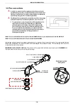
ONLY for use with Horizontal concentric flue kit Ø60/100 mm as per manufacturer’s kit No 82101LP
.
ONLY for use with manufacturer’s flue terminal No 421002060.
Discharges exhaust gases and draws combustion air by means of two concentric ducts. The external Ø100 duct
draws the combustion air while the Ø60 duct discharges the exhaust fumes. The discharge duct must be
connected directly to the outside.
MAXIMUM FLUE LENGTH: 1000 mm, t
he position of the upper disk indicator must only be set to
NUMBER 4
of
the lower disk and remove all the semi-punched tags.
90° FLUE BEND Ø100/60
FIXING SCREW
NEOPRENE SEALING GASKET
FLUE TERMINAL Ø 60
WALL PLATE Ø 100 - RUBBER
FLUE PIPE Ø 60 INT. ALLUMINIUM
FLUE PIPE Ø 100
DOUBLELIP
WASHER Ø 60 RUBBER
ADJUSTABLE
FLUE DIAPHRAGMS
Diaphragm system
setting No 4
3
INDICATOR
5
2
1
4
FOR ADJUSTMENT
NUMBERS


