MAINTENANCE INSTRUCTIONS
20
4.5 Starting up the boiler
Once the system has been filled, proceed as
follows:
•
Check that the exhaust flue is free of
obstructions and correctly connected to the
boiler;
•
Switch on the power supply to the boiler;
•
Open the gas feed valve;
•
Place switch
1
in the ON
position
(see 2.7
“Control Panel”)
,
after a few seconds the
circulating pump will start to run;
•
The boiler will light automatically (with the
WINTER mode selected and room thermostat
connected);
•
The automatic ignition system will then light
the burner. This operation is repeated for 3
times (every 20 seconds) in case of the boiler
should fail to ignite.
It may however be
necessary to repeat the operation in order to
eliminate all the air from the pipes. To repeat the
operation, wait approximately three minutes
before re-attempting to light the boiler. To reset
the boiler switch off switch
1
(fig. 1) and switch it
back on again and repeat the lighting procedure;
•
With the boiler ignited, if the system still emits
noises, the operations must be repeated until all
the air has been removed;
•
Check the pressure in the system. If the
pressure has fallen, re-open the filling tap until
the code
H2O
disappears on the display and the
pressure reaches the middle of the green area
(1,2 bar).
On completion, close the filling tap.
•
set ON/OFF switch
1
in OFF position, insert a
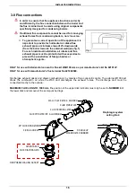
gauge into the pressure point no. 2 (fig. 2). Turn
ON the boiler and check the minimum and
maximum gas pressure setting in accordance
with values stated on the gas data plate. If the
pressure values are not the same as those
stated on the gas data plate, calibrate pressure
again;
•
once the calibration procedure has been
completed, unplug the mains lead or turn off the
mains switch, close the gas feed valve and
remove the gauge from the pressure point;
tighten the screw making sure there are no gas
leaks;
•
after carrying out this operation, return the panel
to its correct position and put the front casing
back;
8
1
2
3
4
5
7
6
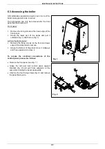
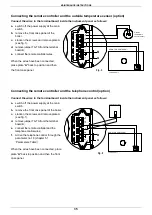
Fig. 1
4
3
2
1
Fig. 2
KEY
1.
GAS ADJUSTMENT SCREW
2.
GAS PRESSURE POINT - OUTLET
3.
GAS PRESSURE POINT – INLET
4.
Adjustment of mechanical minimum gas
pressure


