FFLED18 INSTALLATION INSTRUCTIONS
IMPORTANT
READ CAREFULLY BEFORE INSTALLING FIXTURE. RETAIN THESE INSTRUCTIONS FOR FUTURE REFERENCE
.
RAB fi xtures must be wired in accordance with the National Electrical Code and all applicable local codes. Proper
grounding is required for safety. THIS PRODUCT MUST BE INSTALLED IN ACCORDANCE WITH THE APPLICABLE
INSTALLATION CODE BY A PERSON FAMILIAR WITH THE CONSTRUCTION AND OPERATION OF THE PRODUCT
AND THE HAZARDS INVOLVED.
WARNING: Make certain power is OFF before installing or maintaining fi xture. No user serviceable
parts inside.
Thank you for buying RAB lighting fi xtures. Our goal is to design the best quality products to get the job done right. We’d like to hear your comments.
Call the Marketing Department at 888-RAB-1000, or email: [email protected]
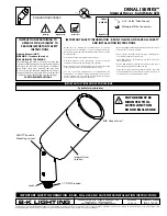
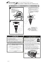
LOCATION
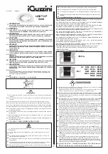
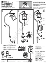
1. Seal arm thread using tefl on tape or silicone sealant.
2. Secure the LED Flood to a 1/2” NPS hole in a
junction box or landscape post.
3. Plug all unused holes and seal threads with silicone.
4. The swivel arm on the LED Flood allows 140º - 150º
of vertical aiming adjustment depending on mounting
location.
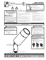
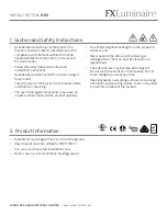
GUARD
or
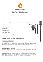
SHIELD INSTALLATION
Wire Guard and Poly Shield mount with (4) #8-32
Stainless Steel Screws.
Screws are provided with
accessory. See fi gure 1 for Guard. See fi gure 2
for Shield
1. Line up guard with pre-existing, pre-drilled holes in
frame as shown, tighten screws.
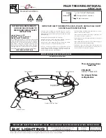
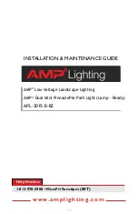
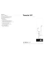
GUARD & SHIELD INSTALLATION
The Wire Guard and Poly Shield can be mounted on the
same fi xture with (4) #8-32 screws as shown below.
Stainless
Steel Screws
Stainless
Steel Screws
Figure 1
Figure 2
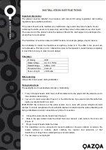
WIRING
Universal voltage drivers permit operation at 120V to
277VAC, 50 or 60 Hz except fi xtures factory ordered
with a 120V photocell (/PC)
1. Connect the BLACK fi xture lead to the
(+) LINE supply lead.
2. Connect the WHITE fi xture lead to the
(-) COMMON supply lead.
3. Connect the bare copper Ground wire from fi xture
to supply ground.