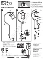
background image

INSTALL NOTE: 

A-NK6

LANDSCAPE & ARCHITECTURAL LIGHTING

   |   Learn more. Visit fxl.com

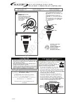
1. Caution and Safety Instructions

•  Qualified personnel must install product in a 

manner consistent with its intended use and in 
compliance with the National Electrical Code, 
Canadian Electrical Code, and/or all Local and 
Provincial Codes.

•  Follow all product label information and 

installation instructions.

•  Qualified personnel must perform all servicing of 

this product.

•  Turn off power at the fuse or circuit breaker before 

installation or servicing.

•  The use of damaged components may cause an 

unsafe condition and void the product warranty.

•  Do not block light emanating from the product in 

whole or part.

•  Never operate the fixture with a missing or 

damaged lens. The lens must be cleaned on a 
regular basis.

•  The entire fixture may become extremely hot. 

Do not touch the hot lens or fixture body. Do not 
touch the light source at any time.

•  Keep all gaskets and sealing surfaces clean during 

installation and servicing; failure to do so may lead 
to premature failure of the product. 

67

IP

2. Product Information

•  Suitable for mounting within 4' (1.2 m) of the ground
•  Vapor barrier must be suitable for 194°F (90°C)
•  For use in non-fire-rated installations only
•  Not for use in environmental air-handling spaces 

3YJ8

Summary of Contents for A-NK6

Page 1: ...damaged components may cause an unsafe condition and void the product warranty Do not block light emanating from the product in whole or part Never operate the fixture with a missing or damaged lens The lens must be cleaned on a regular basis The entire fixture may become extremely hot Do not touch the hot lens or fixture body Do not touch the light source at any time Keep all gaskets and sealing ...

Page 2: ...nockout x3 5 3 135 mm Tools Needed 7 64 Allen key installation 3 Phillips screwdriver installation 1 2 Phillips screwdriver servicing Standard Voltage SV Universal Voltage UV High Voltage HV Input Power 120V 110V to 277V 220V to 240V Dimming Phase 0 10V N A Number of Wires 3 5 3 Black White Green Black White Green Purple Gray Brown Blue Green Yellow Power Requirements ...

Page 3: ... studs For lighting in the downward direction ensure the arrow in the sleeve is pointing upward Wiring Chart North America Wiring Chart International Black Line Hot Switching White Common Green via stud or green lead Ground Gray 0 10V Purple 0 10V FIXTURE FIXTURE BUILDING BUILDING For use with 0 10V driver only For use with 0 10V driver only Front View 3 4 View Brown Line Hot Switching Blue Common...

Page 4: ...the sleeve cover to protect the interior during wall finishing using included fasteners 6 Remove the sleeve cover to resume installation 7 Connect wiring from housing assembly to the incoming power lines using the wiring diagram see previous section and approved wire connectors 8 Insert the complete housing assembly into the construction sleeve 9 Place the housing inside the sleeve and fasten the ...

Page 5: ...he warranty period contact the local authorized manufacturer s representative Hunter s obligation to repair or replace its products as set forth above is the sole and exclusive warranty set forth by Hunter There are no other warranties expressed or implied including warranties of merchantability and fitness for a particular purpose Hunter will not be liable to distributor or any other party in str...

Reviews: