


®
R&M Materials Handling, Inc
STAGEMAKER
®
COMPACT Concert Hoist
Springfield, Ohio USA
SM10 Installation & Maintenance Manual
: 800 955-9967
web:
www.rmhoist.com
June 2006
5 June 2006 10 SM10-M & I MANUAL - 2006 - 0.doc.
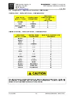
3.2
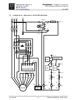
Configuration A – Single Speed – 208 / 230 Volt Connections
Configuration A utilizes direct connection of a three-phase 208 or 230 volt main power supply to the hoist
motor leads via a terminal strip. A motor brake rectifier circuit board (ACF) is provided to operate the
D.C. hoist motor brake assembly.
The above connection diagram shows the connection of the single speed motor windings to the brake
control board. The brake coil supply voltage from the AFC brake control card is 90 - 100 volts DC for
208/230 Volt power supply.
BRK BRK
( #2 ) ( #1 )
(+)
(+)
(-)
(-)
BRAKE LEADS
MOTOR LEADS
JUMPERS
T2 T9
T1
T7 T8
T3 T4 P2
T5
PE
P3
T6
2W
1W/W1
1V/V1
1U/U1
2U
2V
ACF
TERMINAL STRIP
1U
1V
1W
PE
L1
L2
L3
GRD