


®
R&M Materials Handling, Inc
STAGEMAKER
®
COMPACT Concert Hoist
Springfield, Ohio USA
SM10 Installation & Maintenance Manual
: 800 955-9967
web:
www.rmhoist.com
June 2006
5 June 2006 9 SM10-M & I MANUAL - 2006 - 0.doc.
3
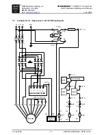
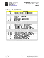
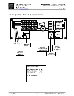
ELECTRICAL CONNECTIONS & DIAGRAMS
The user / owner must provide the main power supply hardware (cable, conductor bar, fuses, disconnect
switch, etc.).
•
Make sure that the power supply voltage is the same as that shown on hoist serial plate / name
plate.
•
Make sure that fuses and other current overload devices are in place to protect the hoist.
•
Make sure that power cable or conductors have sufficient capacity to maintain the hoist supply
voltage by ±5 percent of nominal voltage under all operating conditions. Poor voltage regulation
may cause motor overheating or sluggishness, and chattering / inoperative motor brakes and
controls.
•
Do not use power supply cables with solid conductors.
Before installing, removing, inspection, or performing any maintenance on a hoist, the main
switch shall be de-energized. Lock and tag the main switch in the de-energized position in
accordance with ANSI Z244.1. Follow other maintenance procedures outlined in this manual and
ASME B30.16.
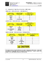
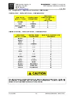
3.1
Control Circuit Fuses
POWER
CONTROL
FUSE SIZE
SUPPLY
VOLTAGE
208V
230V
460V
3 – PHASE
115 VAC
500 mA
500 mA
500 mA
3 – PHASE
48 VAC
630 mA
630 mA
630 mA