EN
.
39
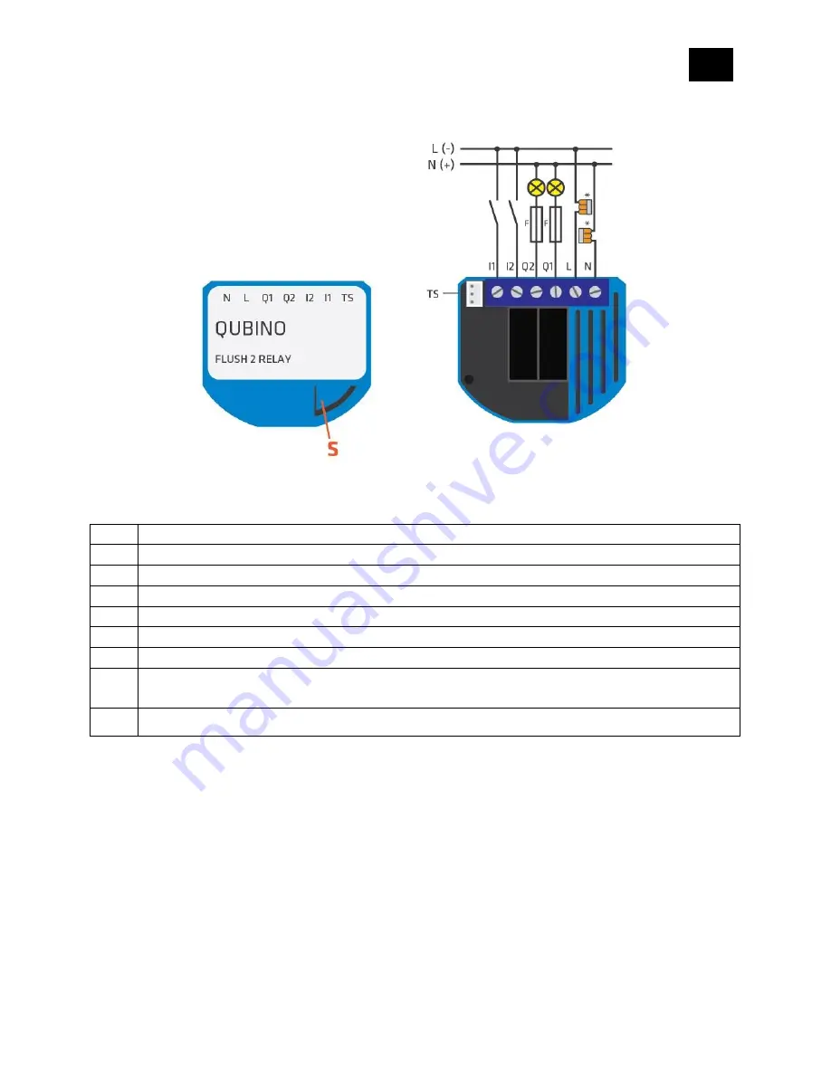
9. Electrical Diagram (110 - 230VAC, 24VDC)
Notes for diagram:
N
Neutral wire (+VDC)
L
Live (line) wire (-VDC)
Q1
⬆
Output for electrical device (load) no. 1
Q2
⬆
Output for electrical device (load) no. 2
I2
Input to control electrical device (in-wall switch) no.2
I1
Input to control electrical device (in-wall switch) no.1
TS
Temperature sensor terminal
*
Wago
221-413 splicing connectors for L and N connection must be used only when
connected to 230 VAC.
S
Service button
WARNING:
The service (S) button
must NOT be used
when the device is connected to a 110-230V power
supply.
The durability of the device depends on the applied load. For resistive loads (light bulbs, etc.)
and 4A current consumption of each individual electrical device, the product’s lifespan exceeds
70,000 toggles for each individual load.
Summary of Contents for Flush 2 relay
Page 17: ...EN 17 4 Package Contents Flush 2 Relay Device Installation Manual...
Page 24: ...EN 24 After Qubino installation...
Page 25: ...EN 25 3 WAY INSTALLATION WITH 2 SWITCHES CONTROLLING THE SAME LIGHT Before Qubino installation...
Page 26: ...EN 26 After Qubino installation when power line and load line are in the same switch box...
Page 27: ...EN 27 After Qubino installation when power line and load line are in different switch boxes...
Page 28: ...EN 28 Before Qubino installation Where there is no neutral line N in switch box...
Page 29: ...EN 29 After Qubino installation Where there is no neutral line N in switch box...
Page 36: ...EN 36 Step 5 Turn the fuse on Step 6 Re include the device to your network...
Page 37: ...EN 37 Step 7 Start using the temperature sensor in connection with your device...


