Right;
The intermediary solar
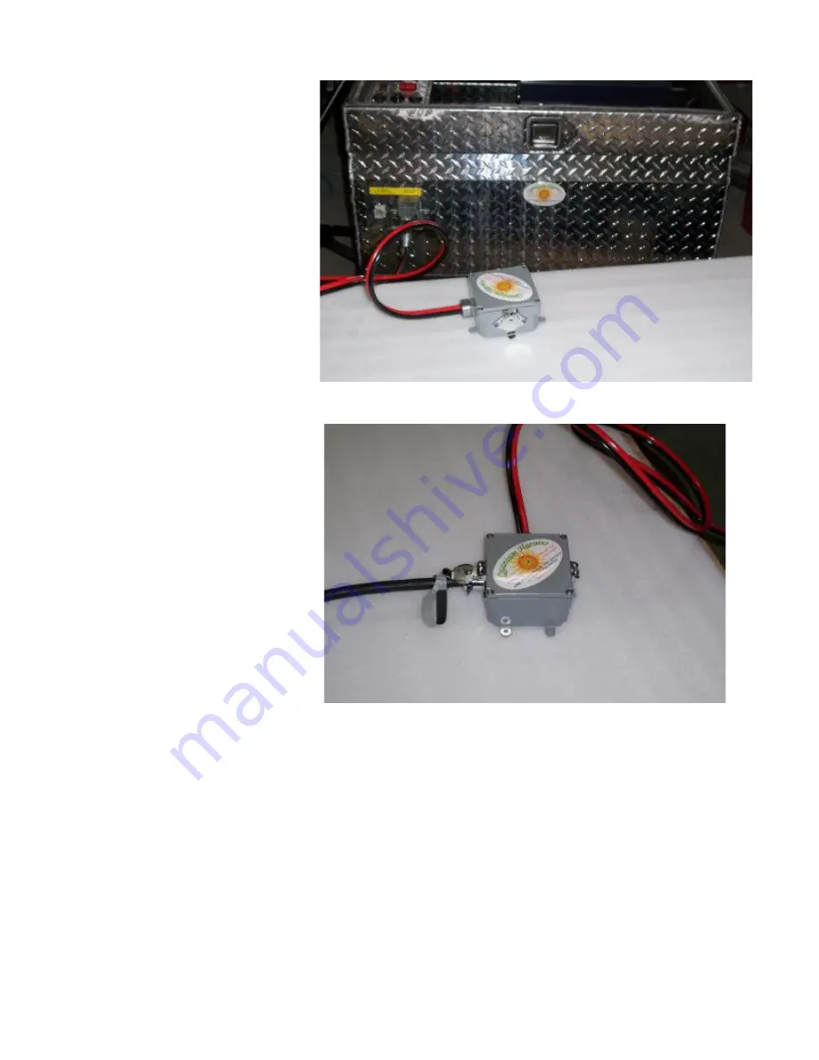
panel cable plugged into the base unit.
The solar panel assemblies simply plug into the intermediary cable junction box
13
Page 1: ...Quantum Harvest Model 3000 60 TSW quantumharvest net Owner s Manual Faraday Enclosures Portable Solar Power Stations...
Page 2: ......
Page 3: ...d but if at all possible strive to avoid doing so Another important component is the inverter This is the device that converts the low voltage DC current from the batteries into the high voltage AC cu...
Page 4: ...e contents The principles involved are fairly simple but the proper execution is critical In order for the enclosure to be useful it must have a door but any opening larger than a square centimeter or...
Page 5: ...Section 4C Using the Solar Panel Assembly s and AC charger Page 16 19 Section 5 Using Booster Cables Page 20 22 Section 6A Power Board Removal Re installation Page 23 25 Section 6B Battery Removal Re...
Page 6: ...ery Charger Solar Charger Controller Instapark 60 Amp MPPT Solar Power Charge Controller Solar Panel Assembly Specifications 300 Watt Model Assembled and folded Dimensions 50 75 H x 8 D x 25 5 W Unfol...
Page 7: ...s will also work Caution Although the low voltage at the battery terminals means that electrical shock or electrocution is impossible nonetheless batteries store an enormous amount of potential energy...
Page 8: ...to a 1 hp submersible well pump It is NOT recommended to power large resistive loads like central air conditioners water heaters and electric space heaters as well as large electric motors such as ind...
Page 9: ...7...
Page 10: ...220 volt system on off switch Polarity indicator LEDs for use with the booster cables see section 5 12 Volt DC cigarette lighter style outlets USB charger ports 2 120 volt AC outlets Inverter start bu...
Page 11: ...20volt outlets 20 amp for 12 volt DC outlets 5 amp for USB charger 20 amp 220 volt AC breaker and soft start module control system Detail of AC Charger Battery voltage selector Battery type selector M...
Page 12: ...connection to battery bank Green light in the middle may be ignored in this application Right The solar charge controller is protected by 2 70 amp circuit breakers It is recommended that they be kept...
Page 13: ...he latch side of the unit External Connector Location AC Charger port Insert the plug into the socket with the silver tab on top and turned slightly to the left Push it in fully and gently twist it cl...
Page 14: ...and oriented as shown with the boss on top slide the connector into the socket Please note that the cover has a latch pawl to prevent the jack from creeping out To remove lift the cover slightly to di...
Page 15: ...Right The intermediary solar panel cable plugged into the base unit The solar panel assemblies simply plug into the intermediary cable junction box 13...
Page 16: ...en so as to allow adequate airflow for inverter cooling Note that it is not necessary to have the solar panels connected in order to use the power station but if they are not connected and in direct s...
Page 17: ...olt system includes our proprietary soft start module pictured on the right It s purpose is to reduce the amount of current required to start the pump motor this allows a smaller load to be passed to...
Page 18: ...lt to be as sturdy as possible but remember that the panels themselves are made of a low iron glass that while quite robust is nonetheless glass and WILL BREAK if the panels are dropped or fall onto a...
Page 19: ...to provide support Right This shows the wheel strut locked in the transport position To unlock pull the gold colored knob out and twist it 90 degrees either way to lock it in the retracted position N...
Page 20: ...elease the rubber latch on top and unfold as shown Be careful to not pinch your fingers between the panels Been there done that Below The top support gusset is velcroed to the back of the middle panel...
Page 21: ...utton Close and latch the cabinet door Note that the main switch should be OFF The AC charger will automatically maintain the batteries at the optimum voltage as long as it is plugged in There is no n...
Page 22: ...t of cables that conveniently mate with a corresponding terminal on the control panel These models also have a unique system to help prevent crossed polarity which again due to the size of the battery...
Page 23: ...then first plug the cables into the power station then affix the clamps to the vehicles battery Step 3 Check for correct cable to battery polarity by looking at the LEDs on the control panel See belo...
Page 24: ...the top 1 2 position If the switch is moved to this or the 2 position when the red LED is lit there will be a dead short between the power station and the car s electrical system This will almost cert...
Page 25: ...ble modules the power assembly which contains the the inverter chargers and related components and the control panel Removal of the power assembly Tools Required 9 16 socket or wrench Main fuse Invert...
Page 26: ...art as shown Due to it s robust design it takes a fair amount of effort to disconnect it It helps to rock one segment from side to side while pulling it apart Step 5 Below Disconnect the 4 connectors...
Page 27: ...ether until you hear a click Step 4 Right Disconnect the inverter control cable It works the same as a phone jack Right After installation be sure the selector switch on the back of the inverter is in...
Page 28: ...art fires and cause personal injury Eye protection MUST BE WORN whenever working with batteries of this size and extreme care must be exercised at all times Anything electrical is unforgiving of mista...
Page 29: ...batteries Battery Installation Instructions Caution Although the low voltage at the battery terminals means that electrical shock or electrocution is impossible nonetheless batteries store an enormou...
Page 30: ...otection at all times Be wary of applying excessive force things should slide in and together smoothly If something seems to go hard it is most likely caught up on something or started crooked Battery...
Page 31: ...ove the power board Pages 21 22 Step 2 Remove the batteries Pages 23 24 Step 3 Below Disconnect the 2 cords red circle and the 2 pin connector green circle Step 3 Right Remove the 4 screws on the hing...
Page 32: ...atteries Pages 23 24 Step 3 Right Using an 11 16 socket or wrench remove the nut indicated and remove the left cable Step 4 Right and below right Remove the nuts from the red and black terminals indic...
Page 33: ...Step 5 Right Remove the screw indicated Step 6 Right Disconnect the 120 volt connector shown here Step 7 Right Disconnect the power wire from the 220 volt transformer feed contactor 31...
Page 34: ...module and the cord that connects the soft starter to the control panel 220 volt outlet Do not remove these 2 nuts Step 9 Above Remove only the 2 acorn nuts indicated lift the control panel up off th...
Page 35: ...ers for the solar but meter indicates 0 charging amps charge controller in the on position No LEDs lit on solar charge controller Page 9 Water pump does not run main switch is on Can you hear a faint...
Page 36: ...sist in diagnosing the problem and either arrange to send you the part at cost or have you ship us the affected module where we will diagnose the problem and contact you with the cost of the replaceme...
Page 37: ...as 3 boxes and 6 diodes in total To gain access to the blocking diodes remove the cover by inserting a thin bladed screwdriver into the slot and gently prying inward to release the catch Repeat for al...
Page 38: ...s in as shown It is VERY IMPORTANT to orient the diodes properly The silver stripe goes in the direction of the arrow Snug the screws back up being very careful not to strip the threads Replace the co...
Page 39: ...e cabinet out of the way Disconnect the inverter main power cable Step 2 Pick up the power board and lay it partially out of the cabinet as shown on the top photo on page 24 This allows access to the...