background image

 Chapter 1 Library Overview

Operator Accessible Components

ACL 4/52 Operator’s Guide

7

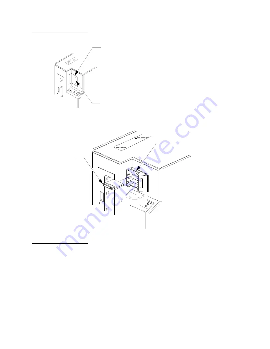
Figure 4  Load Port

Front Door (with 
Interlock Switch)

1

The library door is shown in figure 5. This door can be used to access 
the DLT tape drive status/control panels for manually unloading, 
ejecting and removing a tape cartridge from the drives.

For safety purposes, an interlock switch (shown in Figure 4) removes 
power from the robotics equipment when the door is opened. 
Typically, the front door will be used by FSEs during maintenance 
procedures.

Load Port (Closed)

Cartridge

(View Port)

TA00015B

(Closes to Left)

Load Port (Open)

Summary of Contents for ACL 4/52

Page 1: ...ACL 4 52 Automated Tape Library for DLT Cartridges Operator s Guide 6211222 05 Ver 5 Rel 0...

Page 2: ...dio communications Any changes or modifications made to this equipment may void the user s authority to operate this equipment Operation of this equipment in a residential area may cause interference...

Page 3: ...With all panels and enclosures in place this product is rated as a Class I laser product The bar code scanner inside this product however is a Class II laser Avoid exposure to the laser light emitted...

Page 4: ...g nationale lovbestemmelser Huomautus Nauhakirjastossa on litiumparisto Robottiohjainkortin Dallas Semiconductor DS1230AB 200 puolijohteessa on litiumparisto Litium voidaan luokitella vaaralliseksi ai...

Page 5: ...ede considerarse como un material peligroso Deseche esta pila de acuerdo con las leyes municipales estatales y federales Varning Magnetbandsbiblioteket inneh ller ett litiumbatteri Dallas Semiconducto...

Page 6: ......

Page 7: ...e 16 Configuration Menu Functions 16 Drive Control Menu Functions 17 Diagnostics Menu Functions 18 Chapter 2 Operating Procedures 21 Operating Procedures 22 Applying Power to the Library 22 Placing th...

Page 8: ...on 34 Enabling Disabling the Auto Load Feature 35 Setting Changing the Status Display Area Language 36 Adjusting the Display Area Contrast 37 Unloading a Drive 37 Cleaning a Drive 38 Displaying the Li...

Page 9: ...nel 9 Figure 7 DLT 2000 Tape Drvie Status Control Panel 10 Figure 8 DLT 4000 Tape Drive Status Control Panel 10 Figure 9 DLT 7000 Tape Drive Status Control Panel 11 Figure 10 Menu Structure 13 Figure...

Page 10: ...x ACL 4 52 Operator s Guide...

Page 11: ...perator s Guide Tables Table 1 Control Panel Functions 5 Table 2 DLT Tape Drive Status Control Panel Functions 11 Table 3 Cartridge Tape Drive Campatibility 12 Table 4 Status Messages 44 Table 5 Other...

Page 12: ...xii ACL 4 52 Operator s Guide...

Page 13: ...rovides procedures for applying removing library power inserting removing tapes through the load port manually unloading a tape cartridge and procedures for all functions associated with the Control P...

Page 14: ...where S hexadecimal sense key value AA hexadecimal additional sense code QQ hexadecimal additional sense code qualifierer Related Documents 0 Documents related to the ACL 4 52 are shown below ACL 4 52...

Page 15: ...arters 0 To order documentation on the LANvault 200 or other products contact ATL Products Inc 101 Innovation Drive Irvine CA 92612 5872 949 856 7800 800 284 5101 Technical Publications 0 To comment o...

Page 16: ...America South America 949 477 7940 Europe Africa Asia and Australia International Code 1 949 477 7940 Send e mail for the Professional Services Department to North America South America helpdesk atlp...

Page 17: ...ACL 4 52 Operator s Guide Chapter 1 Library Overview Chapter 1 Library Overview 1 This section contains a brief description of the library and a discussion of each of the operator accessible component...

Page 18: ...communicates with the library through a SCSI interface using the SCSI 2 medium changer command set In a typical operation the host commands the robotics to transfer tape cartridges between storage bin...

Page 19: ...the library menu mode which is viewed in the status display area of the control panel Figure 2 ACL 4 52 Library Numbering Conventions 6 7 1 1 B A Load Port Bins FSA Bins DLT Tape Drives DLT 7000 show...

Page 20: ...rol panel allows you to perform several types of functions operational and diagnostic using the menu mode The menu mode functions and the items listed above are discussed in the following paragraphs C...

Page 21: ...e robotics are parked then unlock the door the indicator is steadily lit Once the indicator is steadily lit you can close the door The library will lock it in the closed position STANDBY button indica...

Page 22: ...e able to decide if an unload operation is necessary Pressing the OPEN button automatically opens the door allowing the operator to remove the tape cartridge s SELECT scroll up and scroll down buttons...

Page 23: ...access the DLT tape drive status control panels for manually unloading ejecting and removing a tape cartridge from the drives For safety purposes an interlock switch shown in Figure 4 removes power f...

Page 24: ...e front door may be opened Always press the control panel STOP button before opening the front door Figure 5 Front Door Rear Panel 1 The rear panel of the library is shown in figure 6 It contains the...

Page 25: ...d on each DLT tape drive figure 7 figure 8 and figure 9 The features of the status control panel are described in table 3 on page 12 For detailed discussions of the DLT tape drive refer to the appropr...

Page 26: ...m p r e s s D e n s i t y O v e r r i d e D e n s i t y 2 6 1 0 0 6 0 O p e r a t e C l e a n i n g T a p e U n l o a d H a n d l e P r o t e c t e d T a p e i n U s e U s e W r i t e TA00040a S e l...

Page 27: ...en indicator lights when the insert release handle is ready to operate Use Cleaning Tape indicator This yellow indicator lights when the drive head needs cleaning or the current cleaning tape is bad A...

Page 28: ...idges which are dark gray and black respectively When loading the library with cartridges observe the compatibility of cartridges and tape drives as defined in table 3 Table 3 Cartridge Tape Drive Cam...

Page 29: ...on the sub menu or function displayed on the lower line is the option selected or executed The overall structure and capabilities of the menu mode are shown in figure 10 on page 13 The functions for w...

Page 30: ...hrough the options list until the desired option is displayed The operator selects the option and it is executed An Exit option is provided at the end of each menu sub menu and option list When the op...

Page 31: ...SCSI ADDRESS Sub Menu Bypass the PWR UP STATE Sub Menu Bypass the NUM OF DRIVES Sub Menu Choos e the AUTO CLEAN Sub Menu Status Display Switch Description M a S u Me nu Con figu ra tion Me nu C on fig...

Page 32: ...Setting Changing the Library s SCSI Address 1 The SCSI address 0 7 of the library can be set using the SCSI Address Robotics sub menus Setting Changing the Tape Drive SCSI Addresses 1 This function i...

Page 33: ...ridges within the library monitors cleaning tape cartridge use and determines when a cleaning tape cartridge has been used up A used up cleaning tape cartridge is exported from the library to the load...

Page 34: ...function use the Clean sub menu The options are Drive 0 Drive 1 Drive 2 Drive 3 where Menu Mode Physical Location Drive 0 Top Drive Drive 1 Second Drive Drive 2 Third Drive Drive 3 Bottom Drive Diagn...

Page 35: ...enu options are reserved for FSEs and are not discussed here For detailed instructions on using the control panel in the menu mode see Chapter 2 Operating Procedures Note With a full library the inven...

Page 36: ...Chapter 1 Library Overview Operator Tasks using the Menu Mode 20 ACL 4 52 Operator s Guide...

Page 37: ...ating Procedures 2 This chapter provides procedures for applying removing power inserting removing tape cartridges through the load port manually unloading a cartridge from a tape drive and performing...

Page 38: ...wer switch to the on position 3 After several seconds verify that SDA shows System On line Note System On line is only displayed if the library power up state is configured for On line Otherwise Syste...

Page 39: ...reign material that may be clinging to the cartridges 1 Press the load port OPEN button and verify the indicator begins blinking It may require several seconds for the load port door to automatically...

Page 40: ...y to be removed press the load port OPEN button and verify the indicator begins blinking It may require several seconds for the load port door to automatically open Warning Mechanical hazards could be...

Page 41: ...anel STOP button before opening the front door 3 Open the front door by pulling the door towards you The door opens to your right Warning The front door is the only location for manually removing tape...

Page 42: ...wn the insert release handle and return to step 4 Otherwise continue to step 7 7 Pull the tape cartridge completely out of the drive 8 Close the library door 9 Press the control panel STOP button 10 P...

Page 43: ...Chapter 2 Operating Procedures Operating Procedures ACL 4 52 Operator s Guide 27 Figure 14 DLT 7000 Manual Unload Unload Button Insert Release Handle Shown in Up Position TA00056b DLT 7000 Front Bezel...

Page 44: ...s the control panel STOP button Warning To prevent injury from moving components always press the control panel STOP button before opening the front door 3 Using a 5 32 hex wrench unlatch the front do...

Page 45: ...perating Procedures Turning the Interior Light On Off ACL 4 52 Operator s Guide 29 Figure 15 Turning the Interior Light On Off TA00038d Power Switch Interior Light Shown in Off Position Opens to Right...

Page 46: ...uage displayed in the SDA Adjusting the SDA contrast level Unloading a tape cartridge from a specific drive Directing cleaning tape cartridges to specific drives for cleaning Performing the initial lo...

Page 47: ...the Library SCSI Address2 To set or change the library SCSI address 1 Enter the menu mode 2 Press the SELECT button to choose the Configuration menu and verify the following is displayed in the SDA 3...

Page 48: ...button again to choose SCSI Address and verify the following is displayed in the SDA 5 Use the button to bypass the Robotics sub menu and verify the following is displayed in the SDA 6 Use the and bu...

Page 49: ...er the menu mode 2 Press the SELECT button to choose the Configuration menu and verify the following is displayed in the SDA 3 Use the button to bypass the Inquiry menu and verify the following is dis...

Page 50: ...ollowing is displayed in the SDA Note Auto Clean Disabled is the default If you want to enable the automatic cleaning proceed to step 6 Otherwise exit the menu mode 5 With the desired option displayed...

Page 51: ...g Disablingthe Auto Load Feature 2 To enable or disable the auto load feature 1 Enter the menu mode 2 Press the SELECT button to choose the Configuration menu 3 Verify the following is displayed in th...

Page 52: ...played in the SDA 4 Use the button to bypass the Inquiry SCSI Address Power Up State Auto Clean Retries and Auto Load sub menus and verify the following is displayed in the SDA Note With Language disp...

Page 53: ...yed in the SDA 5 With Set View displayed on line 2 of the SDA press the SELECT button and verify the following is displayed in the SDA Note Contrast 5 is the default contrast setting If you want to ch...

Page 54: ...ber Drive 0 Top Drive Drive 1 Second Drive Drive 2 Third Drive Drive 3 Bottom Drive 7 With the proper drive number displayed on line 2 press the SELECT button and verify the following is displayed in...

Page 55: ...ve Drive 3 Bottom Drive 8 With the proper drive number displayed on line 2 press the SELECT button and verify the following is displayed Where n the number of the drive that you selected 9 When the fo...

Page 56: ...2 press the SELECT button 7 Use the and buttons to scroll through the SDA line 2 displays to review the information returned Examples are shown below Status Actuator Example 1 51 Horizontal position 1...

Page 57: ...tory displayed on line 2 press the SELECT button Note With a full library the inventory will take less than three minutes if all of the cartridges are properly bar code labeled The actual inventory ti...

Page 58: ...Chapter 2 Operating Procedures Operating Procedures Using the Menu Mode 42 ACL 4 52 Operator s Guide...

Page 59: ...tor Troubleshooting Chapter 3 Operator Troubleshooting 3 This chapter provides explanations of status messages displayed in the Control Panel Status Display Area SDA as well as the associated action n...

Page 60: ...agnostic PC DIAG port or enter the control panel menu mode The library is transitioning from off line to on line but must complete a command that is currently executing When finished System On line is...

Page 61: ...led from off to on this message is displayed in the SDA following the Initializing Wait for On line message When the library successfully completes initialization System On line is displayed in the SD...

Page 62: ...dministrator Table 5 Other Problems Note For any other problem not listed notify your FSEs Problem Resolution A tape drive is not ejecting the cartridges properly 1 Use the procedure Unloading a Tape...

Page 63: ...ice that is mounted on the extension axis that reads the cartridge bar code labels C calibration The software measurements and configuration required for successful operation of the library CHM Cartri...

Page 64: ...fixture mounted inside the library Its purpose is to store up to 48 cartridges in the library FSE Field service engineer G gripper assembly The assembly that mounts on the extension axis and grips ca...

Page 65: ...smetic panel of the library that contains the AC power switch AC power receptacle and connectors for attaching external cabling to the library S SCSI Small computer system interface A communications s...

Page 66: ...50 ACL 4 52 Operator s Guide vertical carriage assembly The crossbar and linear bearings mounted on the vertical rails and all components mounted on the crossbar Z ZIF Connector Zero Insertion Force C...

Page 67: ...menu 17 contrast settings supported 37 drive control menu cleaning 18 unloading 18 F Fixed Storage Array 2 bin numbering 3 Fixed storage array 48 front door 7 12 I inventory elapsed time 19 41 menu 4...

Page 68: ...22 removing 23 power up state menu 16 33 R rear panel 8 retry option menu 17 34 S SCSI address menu setting changing drive 16 32 setting changing library 16 31 SCSI II specification xv SCSI interface...

Reviews: