


FORM QTC2-eg1 (515)
QUANTECH
69
f. motor Current module: Capable of monitoring compressor motor current. Provides ex-
tra protection against compressor reverse rotation, phase-loss and phase imbalance.
option consists of one module per electrical system.
G. Condenser Coil Environmental Protection:
1.
Pre-Coated: Epoxy coated aluminum fin stock to guard from corrosive agents and
insulate against galvanic potential. for mild seashore or industrial locations.
2. Post-Coated dipped: dipped-cured coating on condenser coils for seashore and
other corrosive applications (with the exception of strong alkalis, oxidizers, and wet
bromine, chlorine and fluorine in concentrations greater than 100ppm).
h. Protective Chiller Panels (factory or field mounted)
1. louvered Panels (condenser coils only): Painted steel as per remainder of unit cabi-
net, over external condenser coil faces.
2. Wire Panels (full unit): heavy gauge, welded wire-mesh, PVC -coated to resist cor-
rosion, to protect condenser coils from incidental damage and restrict unauthorized
access to internal components.
3. louvered Panels (full unit): Painted steel as per remainder of unit cabinet, to protect
condenser coils from incidental damage, visually screen internal components, and
prevent unauthorized access to internal components.
4. louvered/Wire Panels: louvered steel panels on external condenser coil faces,
painted as per remainder of unit cabinet. heavy gauge, welded wire-mesh, coated
to resist corrosion, around base of machine to restrict unauthorized access.
i. flow Switch (field-mounted): Vapor proof SPdT, NEmA 4X switch (150 PSiG), -20°f
to 250°f.
J.
Differential Pressure Switch: Alternative to an above mentioned flow switch. A 300 psi
maximum working pressure SPdT 5 amp 125/250VAC switch, with a range of 3-45
PSiG (0.2-3 barg), deadband 0.5 - 0.8 psi, with 1/4” NPTE Pressure Connections.
K. Evaporator options:
1. Provide 1½" cooler insulation in lieu of standard ¾".
2.
Provide Raised Face Flanges for field installation on cooler nozzles and field piping:
a. 150 PSiG, welded flanges.
l. Service isolation valves: Service suction and discharge (ball type) isolation valves are
added to unit per system. This option also includes a system high pressure relief valve
in compliance with AShrAE 15.
m. remote Cooler: manufacturer shall provide separately: chiller less evaporator, leaving
and return water sensors, and liquid line components (solenoid valves, filter driers,
sight glasses, and TXVs), as discrete elements of a complete factory system. Contrac-
tor shall be field erect system and provide interconnecting refrigerant piping and wiring
in accordance with manufacturer recommendations, and project plans and schedules.
Where not otherwise specified, Contractor provided system piping shall be in accor
-
dance with applicable sections of AShrAE handbook.
Guide Specifications (Cont'd)
Summary of Contents for QTC2015T
Page 4: ...QUANTECH FORM QTC2 eg1 515 4 This Page Intentionally Left Blank...
Page 12: ...QUANTECH FORM QTC2 eg1 515 12 This Page Intentionally Left Blank...
Page 25: ...FORM QTC2 eg1 515 QUANTECH 25 Unit Dimensions English Cont d QTC2025T LD18674...
Page 33: ...FORM QTC2 eg1 515 QUANTECH 33 45 1 8 18 1 2 LD18682 Unit Dimensions English Cont d QTC2045T...
Page 47: ...FORM QTC2 eg1 515 QUANTECH 47 Unit Dimensions Metric Cont d QTC2045T 424 LD18702...
Page 57: ...FORM QTC2 eg1 515 QUANTECH 57 Power Wiring LD18707...
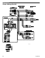
Page 58: ...QUANTECH FORM QTC2 eg1 515 58 LD18744 Power Wiring Cont d...
Page 59: ...FORM QTC2 eg1 515 QUANTECH 59 Power Wiring Cont d LD18746...
Page 60: ...QUANTECH FORM QTC2 eg1 515 60 Factory wired with optional transformer LD03611 Control Wiring...