


QUANTECH
FORM QTC2-eg1 (515)
62
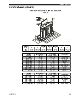
mounting holes (11/16” diameter) are provided in the steel channel for bolting the unit to
its foundation. See dimENSioNS.
for ground level installations, precautions should be taken to protect the unit from tam-
pering by or injury to unauthorized persons. Screws on access panels will prevent casual
tampering; however, further safety precautions, such as unit enclosure options, a fenced-
in enclosure, or locking devices on the panels may be advisable. Check local authorities
for safety regulations.
CHILLED LIQUID PIPING
The chilled liquid piping system should be laid out so that the circulating pump discharges
into the cooler. The inlet and outlet cooler liquid connections are given in dimENSioNS.
hand stop valves are recommended for use in all lines to facilitate servicing. drain con-
nections should be provided at all low points to permit complete drainage of the cooler
and system piping.
The cooler must be protected by a strainer, preferably of 40 mesh, fitted as close as
possible to the liquid inlet connection, and provided with a means of local isolation. The
cooler must not be exposed to flushing velocities or debris released during flushing. it is
recommended that a suitably sized bypass and valve arrangement is installed to allow
flushing of the piping system. The bypass can be used during maintenance to isolate the
heat exchanger o other units.
Pressure gauge connections are recommended for installation in the inlet and outlet water
lines. Gauges are not furnished with the unit and are to be furnished by other suppliers.
The chilled liquid lines that are exposed to outdoor ambients should be wrapped with a
supplemental heater cable and covered with insulation. As an alternative, ethylene glycol
should be added to protect against freezeup during low ambient periods.
A flow switch is available as an accessory on all units. The flow switch (or its equivalent)
must be installed in the leaving water piping of the cooler and must not be used to start
and stop the unit.
Application Data (Cont'd)
Summary of Contents for QTC2015T
Page 4: ...QUANTECH FORM QTC2 eg1 515 4 This Page Intentionally Left Blank...
Page 12: ...QUANTECH FORM QTC2 eg1 515 12 This Page Intentionally Left Blank...
Page 25: ...FORM QTC2 eg1 515 QUANTECH 25 Unit Dimensions English Cont d QTC2025T LD18674...
Page 33: ...FORM QTC2 eg1 515 QUANTECH 33 45 1 8 18 1 2 LD18682 Unit Dimensions English Cont d QTC2045T...
Page 47: ...FORM QTC2 eg1 515 QUANTECH 47 Unit Dimensions Metric Cont d QTC2045T 424 LD18702...
Page 57: ...FORM QTC2 eg1 515 QUANTECH 57 Power Wiring LD18707...
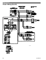
Page 58: ...QUANTECH FORM QTC2 eg1 515 58 LD18744 Power Wiring Cont d...
Page 59: ...FORM QTC2 eg1 515 QUANTECH 59 Power Wiring Cont d LD18746...
Page 60: ...QUANTECH FORM QTC2 eg1 515 60 Factory wired with optional transformer LD03611 Control Wiring...