background image

26

7027-802C

June 4, 2019

CB1200 Free Standing

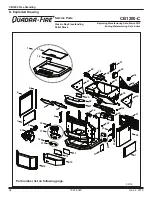
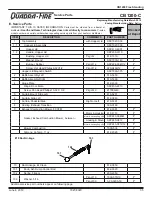
Service Parts Replacement

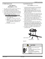
A. Blower Replacement

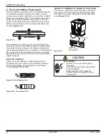
2.  Exhaust Blower Replacement 

PART NUMBER:

 812-3381

Remove existing blower:

a.  Use proper shut down procedures to shut down 

the appliance and let it completely cool and then 

unplug it.

b.  Use an 11/32” wrench or nut driver to loosen and 

remove the (6) nuts holding motor mount plate to 

the blower housing on your appliance.

c. 

Remove washer from beneath the terminal ring on 

the grounding wire.

d. 

Pull motor/mounting plate from blower housing.

e. 

Scrape off old gasket material from blower housing.

Install new blower:

a. 

The blower and blower housing is shipped as an 

assembly. It is necessary to separate them at this 

point if you are using the existing blower housing 

already installed on the appliance.

b.  Follow steps 2 and 3 above. Discard or set aside 

the new blower housing.

c.  Carefully remove gasket from new housing and set 

onto the blower housing.

Re-install blower to blower housing

:

a. 

Install blower on housing ensuring that wiring exits 

facing the 8 o’clock position. Place the washer 

and then the grounding wire on nearest mounting 

plate stud.

b. 

Use nuts removed in 

Step b of Remove existing 

blower

 to secure blower to housing.

c.  Re-connect wiring (use jumper wire if necessary). 

Re-connect power supply.
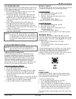
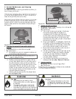
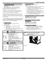
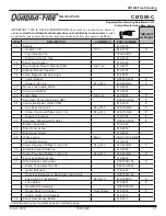
Remove 2 Screws

Remove 4 Screws

Outside Air

Flex Hose

Convection Blower

Figure 28.2

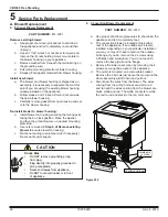
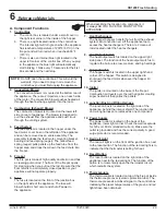
4.  Convection Blower Replacement

PART NUMBER:

 812-3370

a.  Use proper shut down procedures to shut down the 

appliance and let it completely cool.

b.  The convection blower is located at the bottom 

rear of the appliance. If an outside air kit is also 

installed, depending on your particular installation 

you may or may not have to remove the outside 

air flange. If you do, remove the 2 screws using 

a Phillips head screwdriver. You do not need to 

remove the flex pipe from the flange.
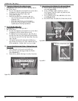
c. 

Remove the lower rear screen by removing the 4 

screws securing the screen to the appliance.

d. 

The motor is mounted on a removable bracket. 

Remove the 2 screws just above the motor and the 

whole assembly will tilt down and pull out.

e. 

Disconnect the wires from the blower. The wires 

coming from the wiring harness are white, red 

and tan and the wires coming from the blower are 

black, white and red. The white connects to white, 

the red to red and black to the tan color wire.
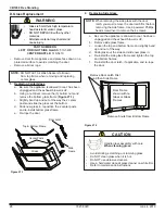
Shock Risk

.

• 

Do NOT remove grounding prong 

from plug.

•  Plug directly into properly grounded 3 

prong receptacle.

•  Route cord away from appliance.

• 

Do NOT route cord under or in front 

of appliance.

CAUTION

Summary of Contents for CLASSIC BAY 1200

Page 1: ...r flammable materials away If the information in these instructions is not followed exactly a fire may result causing property damage personal injury or death WARNING Do not store or use gasoline or o...

Page 2: ...ILE HOMES Do not install appliance in a sleeping room An outside combustion air inlet must be provided The structural integrity of the mobile home floor ceiling and walls must be maintained Refer to m...

Page 3: ...9 C Combustible Materials 9 D Fuel Material and Fuel Storage 9 E Before Your First Fire 10 F Filling the Hopper 10 G General Operating Information 10 H Starting Your First Fire 11 I Fire Characterist...

Page 4: ...ctronic components and glass X X X Factory installed blowers X Molded refractory panels X Ignition Modules X Firepots burnpots mechanical feeders auger assemblies X Vent Free burners Vent Free ceramic...

Page 5: ...anging a warranty call Travel and shipping charges for parts are not covered by this warranty Limited Catalyst Warranty o For wood burning products containing a catalyst the catalyst will be warranted...

Page 6: ...to water or weather damage which is the result of but not limited LIMITATIONS OF LIABILITY have other rights which vary from state to state EXCEPT TO THE EXTENT PROVIDED BY LAW HHT MAKES NO EXPRESS WA...

Page 7: ...r calorifique l efficacit de l aide de donn es recueillies lors d mission de l EPA des tests Une gamme de BTU sorties calcul e l aide de l HHV l efficacit et le taux de br lures de l EPA des tests Bas...

Page 8: ...own to the State of California to cause birth defects or other reproductive harm For more information go to WWW P65Warnings ca gov Improper installation adjustment alteration service or maintenance ca...

Page 9: ...ared to pellets depending on the quality of the corn used Corn must be free of debris Never burn corn straight from the field It will clog the auger mechanism Corn with excessive grain dust must be sc...

Page 10: ...nformation 1 Thermostat Calls For Heat The appliance is like most modern furnaces when the thermostat calls for heat your appliance will automatically light and deliver heat When the room is up to tem...

Page 11: ...short active flame pattern that extends out of the fire pot approximately 4 to 6 inches 102 to 152mm If the fire has tall flames with black tails and seems somewhat lazy the feed rate will need to be...

Page 12: ...ppliance Restart Process 1 When the unit has run out of fuel add pellet fuel to the hopper 2 Dump the ashes and clinkers built up in the fire pot by pulling the ash dump removal handle out several tim...

Page 13: ...ne for Saturday and Sunday Manual Non Programmable In this setting there are no program routines for the thermostat to follow and the temperature control will be set only by the UP and DOWN buttons on...

Page 14: ...l move TEMPERATURE switch to OFF and back to HEAT again Figure 14 1 Q Thermostat Temperature Programs The thermostat by default has 4 separate program events they are MORN DAY EVE and NITE Each event...

Page 15: ...ngs To Lock the Keypad 1 Move TEMPERATURE switch to HEAT 2 Move SET switch to RUN 3 Perform a single press of each button in the following sequence NEXT NEXT NEXT HOLD A padlock will appear on the dis...

Page 16: ...y icon Figure 16 4 Low battery icon Figure 16 2 Power Outlet Terminal Block Center 2 screws for Thermostat Wires CONNECT THERMOSTAT WIRES TO APPLIANCE There is a 4 screw terminal block located on the...

Page 17: ...noisy blowers is from the impellers becoming dirty over time See maintenance and service section for maintaining and servicing What is the metal object with the bend in it that came inside the plastic...

Page 18: ...re OR X Heat Exchanger Drop Tube Every 1 ton of fuel OR X Hopper Every 1 ton of fuel or when changing fuel types OR X Top Vent Adapter More frequently depending on the fuel type or ash build up OR X V...

Page 19: ...ed every time you clean the firebox Remember to place the ash and debris into a metal or noncombustible container e The cleaning rods must be fully closed when cleaning is complete See Disposal of Ash...

Page 20: ...meowner a Be sure the appliance is allowed to cool has been unplugged and the exhaust blower is off b A more thorough cleaning is needed to remove the excess ash that is left behind from the use of th...

Page 21: ...iance is allowed to cool has been unplugged and the exhaust blower is off The products of combustion will contain small particles of fly ash The fly ash will collect in the exhaust venting system and...

Page 22: ...meowner a Be sure the appliance is allowed to cool has been unplugged and the exhaust blower is off b To inspect the door rope gasket open the door and see that the door rope extends approximately 1 8...

Page 23: ...ldup exceeds the half way point in the fire pot IMMEDIATE ATTENTION AND CLEANING IS REQUIRED D Soot or Creosote Fire Establish a routine for the fuel wood burner and firing technique Check daily for c...

Page 24: ...d pellets in fire pot Fire pot clean out plate not closed Fire pot is dirty The ignition hole between the igniter bracket and fire pot is blocked Igniter not working Control box defective Check that f...

Page 25: ...ails to start or does not shut off Blower not plugged in Blower is clogged with ash Blower is defective Control box is defective Check that blower is plugged into wire harness Clean exhaust system Rep...

Page 26: ...tep b of Remove existing blower to secure blower to housing c Re connect wiring use jumper wire if necessary Re connect power supply Remove 2 Screws Remove 4 Screws Outside Air Flex Hose Convection Bl...

Page 27: ...he ash drawer Double check that the igniter wires are clear of any movement i e ash drawer fire pot cleaning rod etc 6 Re install the ash drawer and side panel and re connect the power Igniter Igniter...

Page 28: ...the side frame Use a powered Phillips head screw driver to remove the 4 screws 2 Replacing Side Glass Glass is 5mm thick high temperature heat resistant ceramic glass DO NOT REPLACE with any other mat...

Page 29: ...blue light will automatically start blinking 1 blink every 10 seconds for the first 60 seconds and then will stop 7 Heat Exchangers The heat exchangers transfer hot air from the exhaust system into c...

Page 30: ...m which will turn off the appliance if an over fire condition should occur or if the convection blower should fail to operate 19 Snap Disc 3 Back Burn Protector 250 F Snap disc 3 is mounted on the sid...

Page 31: ...minal Block Center 2 screws for Thermostat Wires Cleaning Rods Heat Exchanger Tubes Figure 32 1 Figure 32 2 Figure 32 3 Heat Output Fan Speed Reset Button Call Light HIGH HIGH MED LOW LOW Outside Air...

Page 32: ...32 7027 802C June 4 2019 CB1200 Free Standing C Service and Maintenance Log Date of Service Performed By Description of Service...

Page 33: ...33 7027 802C June 4 2019 CB1200 Free Standing Date of Service Performed By Description of Service...

Page 34: ...ufacturing Date March 2019 Ending Manufacturing Date Active Classic Bay Freestanding Pellet Stove Part number list on following page 06 19 1 6 2 7 8 9 3 4 5 10 11 12 13 14 15 16 17 17 22 18 19 20 21 2...

Page 35: ...2 220 0490 12 Y Hopper Lid Magnetic Switch SRV7000 375 Y 2 Baffle Assembly Left 510 5350 3 Baffle Assembly Right 510 5360 4 Hinge Plate 812 4030 Hinge Door Male SRV450 2810 Screw Pan Head Phillips 10...

Page 36: ...ement Assembly 18 Loop Igniter Pkg of 1 SRV7000 462 Y Pkg of 10 SRV7000 462 10 Y Wing Thumb Screw 8 32 X 1 2 Pkg of 24 7000 223 24 Y 11 2 Combustion Plenum Trap Door 812 4100 12 Thermocouple Cover Qty...

Page 37: ...y 6 req 229 0640 Y 23 Snap Disc Convection Blower 1 SRV230 0060 Y 24 Convection Blower 130 60 CFM 812 3370 Y Nut Keps Lock 8 32 Pkg of 40 226 0060 40 Y Screw Pan Head Philips 8 32 X 3 4 Pkg of 24 229...

Page 38: ...SRV240 0450 Y 37 Control Board 3 Speed SRV7000 704 Y Fuse 8 Amp Control Box Pkg of 10 812 3780 10 Y 38 Cover Control Box 410 6321 39 Feed Adjustment Plate 812 4170 40 Cover Feed Motor 410 5311 41 Feed...

Page 39: ...SSORIES Collar Offset Top Vent 812 3570 Damper 3 Inch Tall Vertical Installs Only PEL DAMP3 Y Damper 4 Inch Tall Vertical Installs Only PEL DAMP4 Heat Exchange Repair Kit 812 4970 Log Set 811 0592 Out...

Page 40: ...purchased installed _________________________________________________________________________ Serial Number ____________________________________ Location on appliance ___________________________ Deale...

Reviews: