
15
7027-802C
June 4, 2019
CB1200 Free Standing
R. Thermostat Other Features
TEMPERATURE CALIBRATION:
The internal temperature sensor in this thermostat is
accurately calibrated at the factory, and in most cases
alterations to this setting should not be needed. The
temperature calibration feature allows you to manually
offset the measured temperature by as much as plus
or minus 5°F (3°C) from its original value. If several
thermostats are used in the same house, this feature can
be used to synchronize this thermostat to the others.
Change the temperature calibration:
1.
Move TEMPERATURE switch to OFF.
2. Move SET switch to RUN.
3.
Press and hold both UP and DOWN buttons together
for at least 5 seconds; the words SET and CAL will
appear on the display along with a single flashing
temperature digit.
4.
Use the UP or DOWN buttons to change the number of
degrees desired for adjustment; 0° is the default value
and also means no correction will be applied.
5.
Press the NEXT button to accept the setting.
NOTE:
All other features need to be completed in a
timely manner as the thermostat will time out
after 10 seconds.
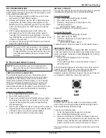
SOFTWARE RESET:
Software reset is used to erase ALL temperature events,
and to return all user-adjustable software settings back to
their original factory default settings.
To Perform a Software Rest:
1. Verify the thermostat’s keypad is not locked.
2.
Move TEMPERATURE switch to OFF.
3.
Press and hold the UP, DOWN, and NEXT buttons all
at the same time for at least 5 seconds. When the LCD
display screen will become fully populated let go of all
buttons at that point the screen will return to normal.
The clock will have to be changed to match the current day
and time.
HW
RST
KEYPAD LOCKOUT:
There is the option to lock the front panel buttons to prevent
unauthorized tampering of your thermostat settings.
To Lock the Keypad:
1. Move TEMPERATURE switch to HEAT.
2. Move SET switch to RUN.
3.
Perform a single press of each button in the
following sequence:
•
NEXT, NEXT, NEXT, HOLD
A padlock will appear on the display screen.
To Unlock the Keypad:
1. Move TEMPERATURE switch to HEAT.
2. Move SET switch to RUN.
3.
Perform a single press of each button in the
following sequence:
•
NEXT, NEXT, NEXT, HOLD
A padlock will no longer be present on the display screen.
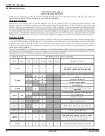
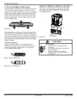
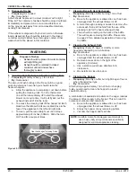
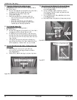
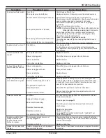
HARDWARE RESET:
The hardware reset button; labeled HW RST, is a small
round push button that is located in the middle of the circuit
board, just below the battery holder
(Figure 16.1)
. Pressing
this button will:
•
Cause the LCD display screen to become
fully populated
• Thermostat to perform an internal system check of
its components
If the thermostat appears to be acting in an erratic manner,
pressing the HW RST button may remedy this behavior.
The temperature programs are not erased when a
hardware reset is performed, however the clock will have to
be changed to match the current day and time.
Figure 16.1
COPY PROGRAM FEATURE:
Using similar instructions as set temperature programs the
COPY button will allow a whole day of set program events
to be copied to another day.
1. Move Temperature switch to HEAT as well as move
SET switch to TEMP PROG position.
2.
Starting with Monday, use the UP or DOWN buttons
to adjust the start time and set temperature for the
MORN, DAY, EVE, and NITE events. Press the COPY
button and then press the NEXT button to advance
to Tuesday.
3.
With Tuesday displayed press COPY button. As
all programs events from Monday will be copied to
Tuesday (this will advance automatically to the next
day; Wednesday, as the word COPY will appear on the
screen for one second).
4.
Continue in this pressing COPY button to set desired
days with original setting.
NOTE:
The word COPY will not appear on the display
for Monday, but will display each day afterwards
for approximately one second and the day of the
week will automatically advance forward to the
next day.


