


November 30, 2017
7014-258B
13
CB1200 FREESTANDING
4
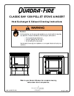
Vent Information
A. Venting Termination Minimum Requirements
J or K
X
V
M
I
H
A
V
G
B
V
V
A
B
V
F V
C
B
B
E
L
V
D
V
Electrical
Service
V
N
V
N
V
N
N
V
Inside Corner
FIXED
CLOSED
OPEN
OPEN
FIXED
CLOSED
V
X
G
G
Termination Cap
Air Supply Inlet
Gas Meter
Restricted Area
O
P
Figure 13.1
A
12 in.
Above Finish Grade (the grade surface
must be a non-combustible material
B
12 in.
48 in. no OAK
Open door or window: below or to the side
B
12 in.
Open door or window: above
C
6 in.
Permanently closed window: above, below
or to the side
D
18 in.
36 in. no OAK
Vertical clearance to a ventilated soffit
located above the terminal within a hori-
zontal distance of 2 ft from the center-line
of the terminal
E
12 in.
Clearance to unventilated soffit
F
12 in.
Clearance to outside corner
G
12 in.
Clearance to inside corner
H
36 in.
Above gas meter/regulator measured from
horizontal center-line of regulator
I
36 in. USA
72 in. Canada
Clearance to service regulator vent outlet
J
12 in.
48 in. no OAK
Clearance to non-mechanical air supply
inlet to the building or the combustions air
inlet to any other appliance
K
10 ft horizontal
3 ft vertical
Clearance to mechanical air supply
L
7 ft.
Above paved sidewalk, paved driveway
located on
public
property
M
12 in.
Under an open veranda, porch, deck or
balcony
N
See Note
below*
Electric service: above, below or to the
side (location must not obstruct or interfere
with access)
O
24 in.
Adjacent building, fences and protruding
parts of the structure
P
12 in.
Clearance above roof line for vertical
terminations
All minimum clearances are listed with an Outside Air Kit (OAK) installed, unless otherwise noted in table below.
24 in.
Above grass, top of plants, wood or any other com-
bustible
12 in.
36 in. no OAK
Clearance from any forced air intake of other appli-
ance
12 in.
Clearance horizontally from combustible wall
15 in.
Vented directly through a wall, minimum length of
horizontal pipe
6 in. horizontal
12 in. vertical
Minimum horizontal or vertical terminations must
protrude from wall
*NOTE:
Consult local building, fire officials or authorities having jurisdic
-
tion. Local codes or regulations may require different clearances.
NOTICE:
Do NOT Terminate Vent:
•
In any location that will allow flue gases or soot from en
-
tering or staining the building
• In any location which could create a nuisance or hazard
•
In any enclosed or semi-enclosed area such as a carport,
garage, attic, crawl space, under a sun deck or porch,
narrow walkway
• Closely fenced area, or any location that can build up
a concentration of fumes such as a stairwell, covered
breezeway, etc.
NOTICE:
Termination must exhaust above air inlet elevation.