


12
TSC-70-G3 and TSC-101-G3 In-Wall Mounting
The TSC-70-G3 and TSC-101-G3 are designed to be installed into dual gang electrical boxes that are common in North America.
A variety of alternate electrical boxes and brackets with similar mounting hole placement may be accommodated, though mounting
procedures for these alternate solutions is not documented here. A dual gang rectangular box with a minimum cavity of 34 cubic inches
is recommended.
IMPORTANT!:
Verify suitability of your selected electrical box, including LAN cable routing, prior to installation.
NOTE:
The countersink holes for the electrical box screws on the wall mount bracket are close to the upper and lower
edges. Care must be taken when creating the wall opening to ensure that no gaps are visible around the wall mount
bracket. The vertical dimension for the wall opening may be dependent on the electrical box selected but should be as
small as possible.
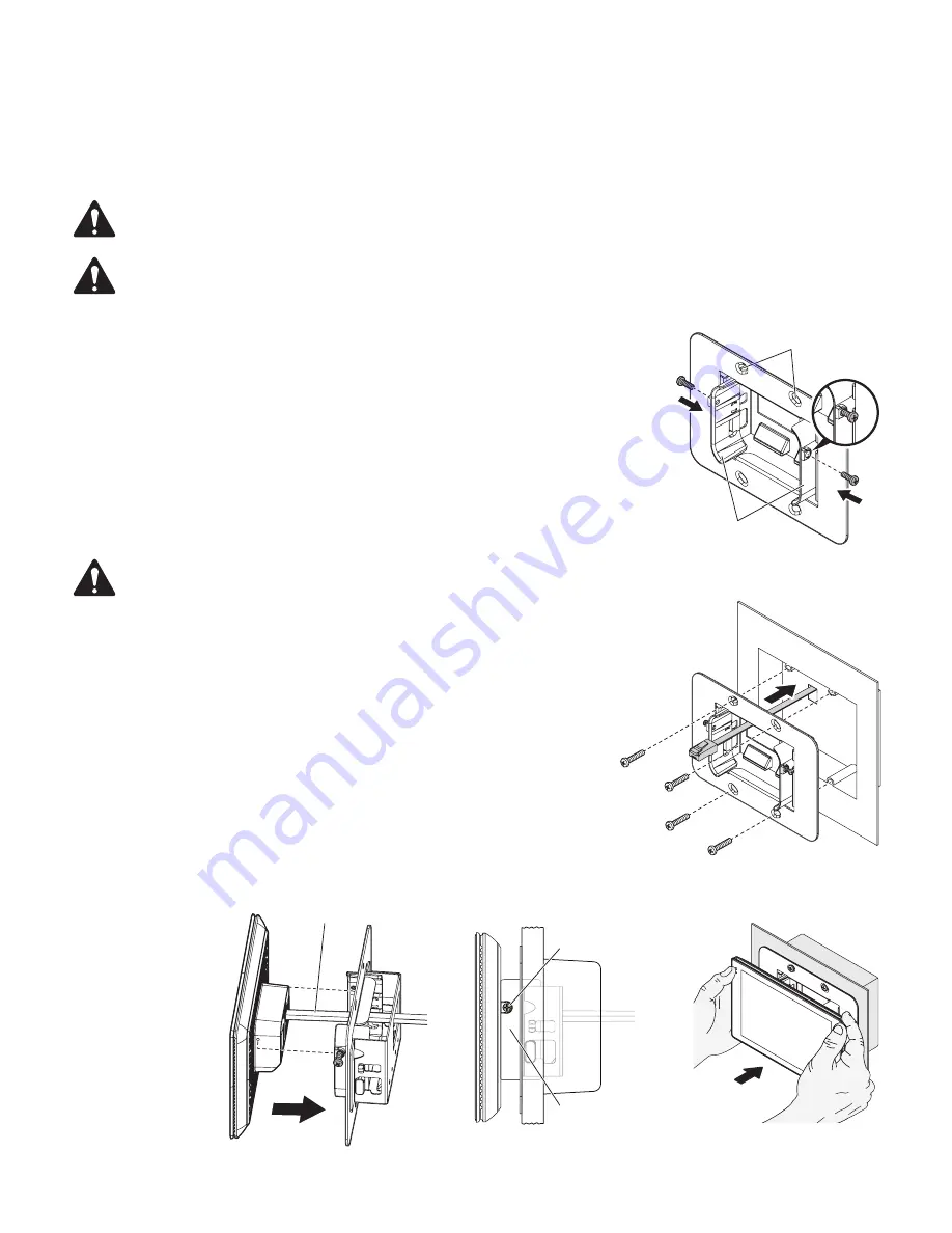
1. Prepare the wall mount bracket for installation by pulling the two plastic mounting wedges
forward until they lock into place. Then partially install two M2.5 screws into the brass
inserts on each mounting wedge. Install the screws only about one full turn. Ensure that
the threaded ends of the screws do not poke through the inner side of the plastic mounting
wedge that mates with the Touch Screen Controller. See — Figure 7.
2. Ensure the LAN cable includes sufficient length to provide proper stress relief.
3. Route the LAN cable through the cable opening in the wall mount bracket. See — Figure 8.
4. Align the wall mount bracket to the electrical box and install using the supplied #6-32
screws. See — Figure 8.
NOTE:
Screws are not supplied for alternate mounting brackets or back boxes.
5. Attach LAN cable to the TSC-70-G3 or TSC-101-G3 rear panel RJ45.
6. Position the Touch Screen Controller between the two mounting wedges of the wall
mount bracket such that the screws installed into the wedges align with the threaded
holes on the two sides of the Touch Screen Controller. See — Figure 9. Using the
supplied screwdriver fasten the screw in each wedge to secure the Touch Screen
Controller. See — Figure 10.
7. Using both hands placed on either side of the Touch Screen Controller, push the
Touch Screen Controller assembly into the wall mount bracket until the magnet on the
unit docks with the wall mount bracket. See — Figure 11. If the rear of the Touch
Screen Controller is not flush with the face of the wall mount bracket (if a gap is
visible), pull the assembly out with both hands and then push it back into the wall
mount bracket. Ensure that the assembly is not pushed in at an angle. This may require
multiple attempts to fully seat the assembly due to the manner in which the mounting
wedges “wedge” into the wall mount bracket to provide a secure fit.
— Figure 7 —
Countersink holes
Mounting wedges
— Figure 8 —
— Figure 9 —
LAN Cable
— Figure 10 —
Mounting wedge
Screw
— Figure 11 —


