Hardware Description (continued)
NOTE: The DCM 10 and DCM 10D have one output for each surround zone and 4 sub outputs.
NOTE: All combining of the individual frequency outputs (2-way, 3-way, or 4-way) is done automatically, so all front panel moni-
toring is of a full frequency signal.
Monitor Volume
: The Monitor Volume control is used to adjust the monitoring volume from the front panel loudspeaker. Rotating the control
clockwise increases the volume. Rotating the control counter-clockwise decreases the volume.
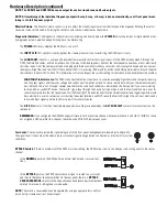
Diagnostic Indicators:
The diagnostics indicator section (including and directly below the
POWER
indicator) provides a simple method of ver-
ifying proper system operation and performing basic troubleshooting.
The
POWER
LED shows whether the DCM unit is on or off.
The
INPUT CLIP
LED is helpful in verifying that the cinema processor is not over-driving the DCM input circuitry.
The
LOAD FAULT
indicator is a unique and powerful feature which verifies that signal inputs into the DCM actually make it through the
DCM, the DataPort cables, and the amplifier unit all the way to the loudspeakers, and that the loudspeaker connections are not electrically
shorted or open. All of these measurements are being performed constantly (without user action) on ALL output channels and any unusual
readings will light the Load Fault LED. If the Load Fault LED is lit, pressing the Amps/Proc button (and holding it pressed) will cause the prob-
lem channel’s indicator LED to blink. This information will let you inspect the system cabling for that channel and troubleshoot the problem.
LOAD FAULT indicator note:
The DCM’s Load Fault detection scheme uses a complex averaging algorithm which compares input sig-
nals to output signals and measures voltage and current on all amplifier outputs. To sense real world conditions, these measurements
must be found to be “out of range” several times before the Load Fault condition is indicated on the front panel. If you are simulating
fault conditions, you MUST have a “real-world” signal level through the device (full signal input), and the fault condition must exist for
several minutes before the front panel Load Fault LED will light. This extra fault verification time eliminates false triggering which would
be confusing to a user. In conclusion, just shorting the output terminals will NOT cause the fault LED to light, the unit must be driven by
real-world input signals and the fault must persist for several minutes.
The
ALT EQ
indicator is lit when the alternate equalization settings are enabled by the
ALT EQ SELECT
contact closure terminals on the
rear panel.
REMEMBER:
If you configured the DCM Manager software to not have certain channels (for example there is no SUB 3 or SUB 4) or have
not assigned a QSC amplifier to a channel, these channels WILL NOT indicate any faults.
Test Jacks:
The test jacks provide the signal being sent to the front panel loudspeaker (pre-level adjust and pre-EQ).
The signal level is the same as the cinema processor output signal (unity gain) and can be used as a test point for system
calibration.
BYPASS Switch
: If there’s a problem with the DCM or system cabling, the DCM active circuitry can be bypassed, routing audio to the center
channel.
In the
NORMAL
position, the DCM performs normal monitor and crossover func-
tions.
In the
BYPASS
position, the PROC center channel signal is routed to a crossover,
and then to the center channel amplifier. On the rear panel, there is a
BYPASS
CROSSOVER MODE
select switch and equalization band level adjustment potenti-
ometers for precisely setting bypass mode audio.
NOTE:
The switch is recessed and can be operated by using an appropriately sized tool
(small flat tip screwdriver, tip of ballpoint pen).


