background image

FEDERAL COMMUNICATIONS COMMISSION (FCC) INFORMATION
NOTE: This equipment has been tested and found to comply with the limits for a class B digital device, pursuant to 
part 15 of the FCC rules. These limits are designed to provide reasonable protection against harmful interference in 
a residential installation. This equipment generates, uses, and can radiate radio frequency energy and if not 
installed and used in accordance to the instructions, may cause harmful interference to radio communications. 
However, there is no guarantee that interference will not occur in
a particular installation. If this equipment does cause harmful interference to radio or television reception, which 
can be determined by switching the equipment off and on, the user is encouraged to try to correct the interference 
by one or more of the following measures:
- Reorient or relocate the receiving antenna.
- Increase the separation between the equipment and the receiver.
- Connect the equipment into an outlet on a circuit different from that to which the receiver is connected.
- Consult the dealer or an experienced radio or TV technician for help.

 THIS PRODUCT IS INTENDED FOR CONNECTION TO A TN OR IT POWER SYSTEM SPECIFICALLY FOR
 NORWAY POWER DISTRIBUTION SYSTEM.

© Copyright  2007 QSC Audio Products, Inc. All rights reserved.

QSC® is a registered trademark of QSC Audio Products, Inc., DCM Manager is a trademark of QSC Audio Products, Inc.

“QSC” and the QSC logo are registered with the U.S. Patent and Trademark Office.

Windows and Windows XP, 2000, and VISTA are trademarks of Microsoft Corporation. 

IBM is a registered trademark of IBM Corporation; Pentium is a registered trademark of Intel Corporation.


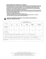
有毒有害物质或元素 

 (Toxic or hazardous Substances and Elements ) 

部件名称 

 (Part Name) 

铅 

 (Pb) 

汞 

 (Hg) 

镉 


(Cd) 

六价铬 

 (Cr(vi)) 

多溴联苯 


(PBB) 

多溴二苯醚 

 (PBDE) 

电路板组件


(PCB Assemblies)


        X 

  
        O 

  
         O 

        
           O 

             
             O 

             
                 O 


机壳装配件


(Chassis Assemblies)


        O 

 
        O              

 
        X 

 
           O 

 
             O 

 
                  O 

O

: 表明这些有毒或有害物质在部件使用的同类材料中的含量是在 SJ/T11363_2006极限的要求之下。


O: Indicates that this toxic or hazardous substance contained in all of the homogeneous materials for this part is below the limit requirement in SJ/T11363-2006.  

X

表明这些有毒或有害物质在部件使用的同类材料中至少有一种而含量是在SJ/T11363_2006极限的要求之上。 

X: Indicates that this toxic or hazardous substance contained in at least one of the homogeneous materials used for this part is above the limit requirement in 
SJ/T11363-2006.


Summary of Contents for DCM 10

Page 1: ...DCM Series Digital Cinema Monitor Crossover System User Manual DCM 10 DCM 10D DCM 30 DCM 30D TD 000265 00 TD 000265 00 A...

Page 2: ...or moisture does not operate normally or has been dropped 15 When installing equipment into a rack distribute the units evenly Otherwise hazardous conditions may be created by an uneven weight distri...

Page 3: ...circuit different from that to which the receiver is connected Consult the dealer or an experienced radio or TV technician for help THIS PRODUCT IS INTENDED FOR CONNECTION TO A TN OR IT POWER SYSTEM S...

Page 4: ...ng Control In addition to the monitoring of your amplifier s audio I O your DCM includes QSC s exclusive Load Fault detection feature The DCM monitors for possible loudspeaker system or wiring faults...

Page 5: ...he signal from analog to digital and back again which is designed to minimize all background noise and react to the dynamic range of any film track 4 Loudspeaker Database pre programmed settings QSC h...

Page 6: ...Monitor Loudspeaker On the rear panel are a set of screw terminals marked EXTERNAL SPKR These are for connection to an external monitor loudspeaker As shipped from the factory a jumper between the IN...

Page 7: ...4 Subwoofer output 5 Alternate equalization select input 6 Auxiliary audio input 7 Hearing impaired output 8 Emergency bypass level controls and switch 9 Main analog input from cinema processor 10 Ana...

Page 8: ...ermines the function of the Monitoring Select but tons to the right of the AMPS PROC button The LEDs directly over the AMPS PROC button indicate what selected function the Monitor Select buttons will...

Page 9: ...t on all amplifier outputs To sense real world conditions these measurements must be found to be out of range several times before the Load Fault condition is indicated on the front panel If you are s...

Page 10: ...io power INPUT SELECT Switch Use this switch to select the input source of the DCM In the ANALOG position input is from the MAIN ANALOG INPUT and the SURROUND EX INPUT if this option is installed If t...

Page 11: ...nal to the EXTERNAL SPKR terminal SUB OUT provides the identical audio as the subwoofer DataPort This connection cannot be monitored or include any of the Fault Analysis functions because there are no...

Page 12: ...chassis and rack can be damaged if the DCM is not properly supported Unless the DCM is being installed in its final fixed location QSC strongly recommends supporting the rear of the unit Rear rack ear...

Page 13: ...ettings to the DCM hardware s flash memory and the DCM hardware can be disconnected from the host PC NOTE QSC updates these files regularly as new models are introduced from loudspeaker manufacturers...

Page 14: ...operating voltage information printed on it Locate the sticker note the rated voltage and ensure the AC circuit you intend to use is properly rated Locate the IEC style AC power cord supplied with yo...

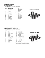
Page 15: ...Ch 1 and Subcode 1 4 I MON Ch 1 and Subcode 2 5 Clip Protect Ch 1 6 Hard Ground 7 Ch 1 Plus Signal 8 Ch 2 Plus Signal 9 15V from Amplifier 10 Data Reference Ground 11 Ch 2 Minus Signal 12 Amplifier I...

Page 16: ...Description 1 not used 2 not used 3 Back Surround Left 4 not used 5 not used 6 Back Surround Right 7 Ground Digital Inputs 8 not used 9 Right Extra 10 Surround Left 11 Surround Right 12 not used 13 no...

Page 17: ...T 22 AES4 Bsl Bsr OUT 23 AES2 C SW OUT 24 AES2 C SW OUT 25 Chassis Ground Hearing Impaired The Hearing Impaired output signal is available on the screw terminal connector on the rear of the DCM The ou...

Page 18: ...oise pick up than unbalanced connections External Speaker Connection The monitor signal is available on the screw terminals at the rear of the DCM This pow ered signal can be connected directly to an...

Page 19: ...to the sound while in the Bypass position While in the bypassed position adjust the potentiometers to most closely match the normal position sound 3 Monitoring audio mix adjustments The DCM Manager s...

Page 20: ...audible but all attempts to get it louder fail connect the DCM to a PC running DCM Manager software and check the Monitor Attenuation Levels settings on the Monitor Setting page These settings have a...

Page 21: ...f switching the BYPASS to EMERGENCY does not restore sound to the center channel Verify the DCM is receiving input signals from the Cinema Processor Verify connections from the Cinema Processor to the...

Page 22: ...0 01 Analog in 0 008 Digital in 20 Hz to 20 kHz all filters flat Frequency Response 20 Hz to 20 kHz D to A Conversion 24 bit delta sigma 128x oversampled Filter Topology 24 bit digital IIR Crossover...

Page 23: ...Dimensions 19 wide x 5 25 high x 15 deep Weight 16 5 lbs 7 2 kg Line Voltage 100 VAC 240 VAC 50 60 Hz Safety Agency Approvals UL 60950 1 CSA RoHS WEE IEC 60950 1 EMC Approvals FCC Class B Connectors...

Page 24: ...ions via pre paid transportation with a copy of proof of purchase i e sales receipt This warranty provides that the examination of the return product must indicate in our judgment a manufacturing defe...

Reviews: