background image

6. Connect all cables and external attachments.

7. Connect the power cord to the electrical outlet.

8. Power on the device.

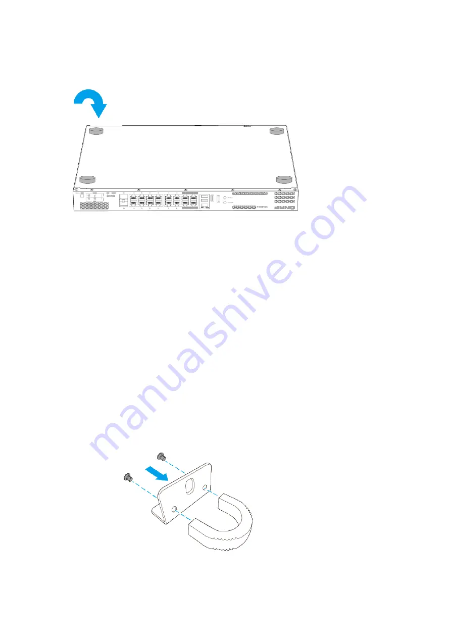
Installing Handles

Installing handles enables you to better grip and secure the device on a rack.

1. Power off the device

2. Disconnect the power cord from the electrical outlet.

3. Disconnect all cables and external attachments.

4. Install a handle on an angle bracket.

a. Align the openings on the handle with the two round screw holes on the angle bracket.

b. Attach the screws to lock the handle to the angle bracket. 

QGD Rackmount Switch User Guide

Installation and Configuration   

35

Summary of Contents for QGD-1602P

Page 1: ...QGD Rackmount Switch QGD 1600P QGD 1602P User Guide Document Version 4 03 03 2023...

Page 2: ...Rubber Feet 33 Installing Handles 35 Fan Installation 36 Connecting the Device to a Computer or Network 41 Connecting USB Expansion Units 42 QTS Installation 43 Installing QTS Using Qfinder Pro 44 Ins...

Page 3: ...Settings 68 Configuring Port Mirroring 68 Enabling LLDP on the Switch 69 Configuring Loop Protection 69 Deleting a Network Setting 70 Monitoring Network Settings 70 System Management 71 Configuring Co...

Page 4: ...UKCA Notice 86 FCC Notice 86 VCCI Notice 87 BSMI Notice 87 SJ T 11364 2006 88 QGD Rackmount Switch User Guide 3...

Page 5: ...user has a basic understanding of storage and backup concepts Document Conventions Symbol Description Notes provide default configuration settings and other supplementary information Important notes p...

Page 6: ...tion User Guide Hardware Specifications Warning If your QNAP product has hardware defects return the product to QNAP or a QNAP authorized service center for maintenance or replacement Any attempt to r...

Page 7: ...Flash memory 4 GB dual boot OS protection Storage Drive bays 2 x 2 5 inch SATA 6 Gbps Note The drive bays are backward compatible with SATA 3 Gbps drives Drive compatibility 2 5 inch SATA hard disk dr...

Page 8: ...W Ports 1 to 4 Up to 90W Ports 5 to 16 Up to 30W Total PoE power budget 260W 200W 370W Warning To reduce the risk of fire or electric shock ensure that you only connect the power cord to a properly gr...

Page 9: ...Accessories Store System battery CR2032 lithium battery 3V 225 mAh Fans System 2 x 40 mm 12V DC fans Drive bay 1 x 40 mm 12V DC fan System 3 x 40 mm 12V DC fans Drive bay 1 x 40 mm 12V DC fan Operati...

Page 10: ...button 9 Switch reset button 3 Host port 10 USB 2 0 Type A ports 4 Gigabit 802 3bt PoE ports 11 USB 3 0 Type A port 5 Gigabit 802 3at PoE ports 12 HDMI 2 0 port 6 Gigabit 802 3at PoE SFP combo ports...

Page 11: ...n 9 10 Gigabit SFP ports 3 USB 3 0 Type A ports 10 Host power button 4 5 Gigabit host ports 11 Switch reset button 5 Gigabit host ports 12 QTS reset button 6 2 5 Gigabit 802 3bt PoE ports 13 LCD selec...

Page 12: ...Combo port speed LED 10 Switch status LED 4 Combo port activity LED 11 Gigabit 802 3at PoE port speed LED 5 QTS status LED 12 Gigabit 802 3at PoE port activity LED 6 Drive 1 LED 13 Gigabit 802 3bt Po...

Page 13: ...Gigabit 802 3at PoE port speed LED 5 10 Gigabit SFP port speed LED 14 Gigabit 802 3at PoE port activity LED 6 10 Gigabit SFP port activity LED 15 2 5 Gigabit 802 3at PoE port speed LED 7 QTS status LE...

Page 14: ...r input 3 System fans 2 System power switch 4 PCIe full height covers System Board QGD 1600P No Component No Component 1 Memory slot 2 5 Drive connector 1 2 Memory slot 1 6 Drive connector 2 QGD Rackm...

Page 15: ...n General Instructions The device should be stored in a secure location with restricted access controlled through the use of a tool lock and key or any means of security Only qualified skilled and aut...

Page 16: ...ep your body parts away from moving fan blades while the device is connected to a power source Moving components Keep your body parts away from other moving components The device is not suitable for u...

Page 17: ...ails see Installation Requirements 2 Install drives For details see the following topics Installing 2 5 Inch Drives Installing M 2 Solid State Drives on the QGD 1602P 3 Optional Install expansion card...

Page 18: ...ting other devices Removing the Case Cover Warning Moving fan blades Keep your hands and other body parts away from moving fan blades Other moving components Keep your hands and other body parts away...

Page 19: ...back c Lift the cover off the device Attaching the Case Cover Warning Moving fan blades Keep your hands and other body parts away from moving fan blades QGD Rackmount Switch User Guide Installation an...

Page 20: ...parts away from other moving components 1 Attach the case cover a Place the cover on the device b Slide the cover forward c Attach the screws 2 Connect all cables and external attachments QGD Rackmou...

Page 21: ...inch solid state drives Warning Installing a drive deletes all data on the drive Observe electrostatic discharge ESD procedures to avoid damage to components Moving fan blades Keep your hands and othe...

Page 22: ...4 Install the drive onto the drive module a Insert the drive into the slot b Attach the screws QGD Rackmount Switch User Guide Installation and Configuration 21...

Page 23: ...tor to the system board b Insert the drive module and connect it to the system board c Attach the screws 6 Attach the case cover For details see Attaching the Case Cover 7 Power on the device QGD Rack...

Page 24: ...lling heatsinks on the M 2 SSD controllers to enhance cooling efficiency and to ensure consistent performance Before installing non QNAP heatsinks ensure that they are of the appropriate size and shap...

Page 25: ...6 Optional Remove an existing M 2 SSD a Remove the screw b Pull the M 2 SSD away from the slot 7 Install the new M 2 SSD a Insert the M 2 SSD into the slot b Attach the screw QGD Rackmount Switch User...

Page 26: ...s two pre installed memory modules You can increase the memory capacity of the device by upgrading the memory modules When using two modules use only QNAP modules of the same type and capacity to main...

Page 27: ...power cord from the electrical outlet 3 Disconnect all cables and external attachments 4 Remove the case cover For details see Removing the Case Cover 5 Optional Remove an existing module a Push the r...

Page 28: ...from the slot Warning Attempting to remove a module that is not completely released may damage the module and the system board c Hold the module by the edges d Carefully slide the module out of the s...

Page 29: ...ot b Insert the module into the slot c Verify that the metal connectors are completely inserted into the slot d Carefully press down on the module until the retention clips lock the module into place...

Page 30: ...purchased from the company website are shipped with the brackets necessary to fit the device For details on supported expansion cards and brackets go to http www qnap com compatibility Warning Observe...

Page 31: ...ving the Case Cover Warning To avoid potential injury or damage to components ensure that the drives and other internal system components have cooled before touching them 5 Remove the expansion card m...

Page 32: ...module 6 Remove the PCIe cover a Remove the screw that secures the cover to the module b Pull the cover away from the slot 7 Install the expansion card a Hold the card by the edges b Insert the card...

Page 33: ...lign the module connector with the system board b Slide the module to the left until it is completely connected with the system board c Attach the screws inside the chassis QGD Rackmount Switch User G...

Page 34: ...etails see Attaching the Case Cover 10 Connect all cables and external attachments 11 Connect the power cord to the electrical outlet 12 Power on the device Attaching Rubber Feet 1 Power off the devic...

Page 35: ...les and external attachments 4 Turn the device upside down 5 Attach the rubber feet a Remove the protective film from the rubber feet b Attach the rubber feet c Place the device in its normal upright...

Page 36: ...device on a rack 1 Power off the device 2 Disconnect the power cord from the electrical outlet 3 Disconnect all cables and external attachments 4 Install a handle on an angle bracket a Align the open...

Page 37: ...hassis 7 Connect all cables and external attachments 8 Connect the power cord to the electrical outlet 9 Power on the device Fan Installation The device contains replaceable system and drive bay fans...

Page 38: ...or details see Removing the Case Cover 5 Remove the fan a Detach the fan s power connector from the system board b Remove the screws that secure the fan to the chassis c Remove the fan from the chassi...

Page 39: ...harge ESD procedures to avoid damage to components Moving fan blades Keep your hands and other body parts away from moving fan blades Other moving components Keep your hands and other body parts away...

Page 40: ...stem board b Remove the screws that secure the fan module to the chassis c Lift the fan module from the chassis 6 Remove the fan a Remove the screws that secure the fan to the fan module b Remove the...

Page 41: ...the fan module to the screw holes on the chassis b Attach the screws that secure the fan module to the chassis c Attach the fan s power connector to the system board 9 Attach the case cover For detail...

Page 42: ...a computer to configure the device settings 1 Power on the device 2 Connect the device to a computer a Connect an Ethernet cable to a PoE port on the device b Connect the Ethernet cable to a Gigabit E...

Page 43: ...upports USB expansion units Refer to the following table for details For the list of compatible expansion units and the maximum number of applicable expansion units go to https www qnap com go compati...

Page 44: ...a Log on to QTS as administrator b Go to Main Menu Storage Snapshots Overview System c Verify that the expansion units are listed QTS Installation The device uses the QNAP QTS operating system You can...

Page 45: ...supports HDMI output you can do the following Connect the device to the required hardware Complete the steps in the Smart Installation Guide wizard Monitor HDMI cable USB keyboard or Remote control no...

Page 46: ...g information NAS name Specify a name with 1 to 14 characters The name supports letters A to Z a to z numbers 0 to 9 and hyphens but cannot end with a hyphen Username Specify an administrator username...

Page 47: ...Obtain an IP address automatically DHCP Select Obtain an IP address automatically DHCP The system automatically detects and configures the IP address settings Use static IP address a Select Use static...

Page 48: ...your device from the list and then click Initialize Note If your device is not listed follow the instructions on the web page to specify the Cloud Key on the device The installation wizard opens in th...

Page 49: ...e Specify an administrator username that contains 1 to 32 characters The name supports letters A to Z a to z numbers 0 to 9 and hyphens multi byte Chinese Japanese Korean and Russian characters The us...

Page 50: ...omatically detects and configures the IP address settings Use static IP address a Select Use static IP address The IP address configuration page appears b Specify the following IP address configuratio...

Page 51: ...cters The name supports letters A to Z a to z numbers 0 to 9 and hyphens multi byte Chinese Japanese Korean and Russian characters The username cannot contain the following special characters grave ac...

Page 52: ...Run Qfinder Pro on a computer that is connected to the same local area network Note To download Qfinder Pro go to https www qnap com utilities 4 Enter the switch IP address The switch IP address will...

Page 53: ...r more details see the QTS User Guide 1 Power on the device 2 Log on to QTS Note For details see Connecting the Device to a Network 3 Go to Main Menu QuNetSwitch 4 Continue with switch management Note...

Page 54: ...m administrator password The default password is the first MAC address in uppercase letters without special characters For example if the first MAC address is 00 08 9B F6 15 75 then the admin password...

Page 55: ...tings for each network adapter on the device IP address Subnet mask Default gateway Primary DNS Secondary DNS 1 Press Enter or Select The panel displays the device name and QTS version 2 Press and hol...

Page 56: ...alled in the device 1 Press Enter or Select The panel displays the device name and QTS version 2 Press and hold Enter for two seconds The panel displays Main Menu 1 TCP IP 3 Press Enter repeatedly unt...

Page 57: ...panel displays Main Menu 6 Reboot 4 Press and hold Enter The device restarts Changing the LCD Password Specifying a password for the LCD panel prevents unauthorized access 1 Press Enter or Select The...

Page 58: ...d Volume has unmounted Vol Nonactive Volume is inactive LEDs LEDs indicate system status and related information when the device is powered on For details on the location of the LEDs see Front Panel L...

Page 59: ...No link was detected Combo Port activity link Flashes amber every 1 0 sec Data is being transferred Audio Alert Duration Frequency Description Short beep 0 5 seconds 1 The device is starting up The d...

Page 60: ...anagement of the switch QuNetSwitch is a switch utility that allows you to manage network configurations of the switch on the QTS operating system With its intuitive interface QuNetSwitch makes it eas...

Page 61: ...ed screen 3 Toolbar The toolbar displays the following information USER_NAME Click to access the Log out button Click to view the following Restart Switch Restarts the switch Help Opens the interface...

Page 62: ...open QuNetSwitch in QTS 2 Go to Devices MAC History 3 Identify a connected device 4 Click The Send WoL Command window opens 5 Specify a MAC address 6 Click Wake QSS or QuNetSwitch sends a WoL command...

Page 63: ...State Controls the operation status for a port Speed Specifies the maximum speed at which a port can operate Flow Control Controls the flow control status for a port Important Flow Control is not sup...

Page 64: ...n window opens 7 Configure the schedule a Optional Select additional ports Selected ports will also be included in the schedule b Select port operating hours c Optional Select Activate schedule now 8...

Page 65: ...twork loop errors during the LAG configuration process do not connect the switch to other devices using more than one network cable until after you have configured LAGs on all the devices You can enab...

Page 66: ...ulticast flooding from unknown sources Router Port Specifies which ports to use as the router port for the VLAN After receiving an IGMP packet QuNetSwitch forwards the traffic through the selected rou...

Page 67: ...e c Optional Specify an egress rate Note You must deselect Unlimited to set an egress rate Tip Click Match rates to use the same ingress and egress rates 6 Click Save QSS or QuNetSwitch saves the rate...

Page 68: ...y the ACL rule or select All to apply the rule to all ports Permission Select one of the following Allow Deny 5 Click Save QSS or QuNetSwitch adds the IP address based ACL rule Adding a MAC Address Ba...

Page 69: ...ased Prioritizes traffic for each port VLAN based Prioritizes traffic for each VLAN 5 Configure the priority Note Larger numbers are given greater priority 6 Click Apply QSS or QuNetSwitch saves the Q...

Page 70: ...ion from neighboring ports connected by a network link The LLDP page displays information about detected devices and allows you to enable and disable LLDP 1 Log in to QSS or open QuNetSwitch in QTS 2...

Page 71: ...is applicable only to link aggregation groups static MAC addresses and VLANs 4 Click A confirmation message appears 5 Click Delete Monitoring Network Settings You can monitor the following network set...

Page 72: ...ystem Management The System section provides access to device configuration options Configuring Connection Settings 1 Log in to QSS or open QuNetSwitch in QTS 2 Go to System Management Settings IP 3 C...

Page 73: ...n at the correct time 1 Log in to QSS or open QuNetSwitch in QTS 2 Go to System Management Settings Time 3 Specify the date time format 4 Specify the time configuration Setting Description Synchronize...

Page 74: ...o to System Management Settings Factory Reset 3 Click Factory Reset A confirmation message appears 4 Click Yes QSS or QuNetSwitch resets the switch to the factory default settings Note To log in to th...

Page 75: ...e switch CPU QTS CPU temperature Displays the real time temperature of the storage CPU System temperature Displays the overall real time temperature of the switch PoE controller temperature Displays t...

Page 76: ...t for 20 seconds or until the device beeps twice 7 Install the new drive The device beeps twice 8 Go to Main Menu Storage Snapshots Storage Storage Snapshots 9 Locate the volume that contains the new...

Page 77: ...sion Unit Compatibility https www qnap com go compatibility expansion Service Portal https service qnap com Product Support Status https www qnap com go product eol php Downloads https download qnap c...

Page 78: ...QNAP devices over the internet without configuring complex port forwarding settings Qfinder Pro QNAP utility that lets you locate and access QNAP NAS devices in your local area network QSS QNAP switch...

Page 79: ...uential damages resulting from the use of the product its accompanying software or its documentation QNAP makes no warranty or representation expressed implied or statutory with respect to its product...

Page 80: ...ou must make sure that they too receive or can get the source code And you must show them these terms so they know their rights Developers that use the GNU GPL protect your rights with two steps 1 ass...

Page 81: ...normal form of packaging a Major Component but which is not part of that Major Component and b serves only to enable use of the work with that Major Component or to implement a Standard Interface for...

Page 82: ...ified Source Versions You may convey a work based on the Program or the modifications to produce it from the Program in the form of source code under the terms of section 4 provided that you also meet...

Page 83: ...ry need not be included in conveying the object code work A User Product is either 1 a consumer product which means any tangible personal property which is normally used for personal family or househo...

Page 84: ...s as different from the original version or d Limiting the use for publicity purposes of names of licensors or authors of the material or e Declining to grant rights under trademark law for use of som...

Page 85: ...reasonable efforts You may not impose any further restrictions on the exercise of the rights granted or affirmed under this License For example you may not impose a license fee royalty or other charge...

Page 86: ...ertinent obligations then as a consequence you may not convey it at all For example if you agree to terms that obligate you to collect a royalty for further conveying from those to whom you convey the...

Page 87: ...ERED INACCURATE OR LOSSES SUSTAINED BY YOU OR THIRD PARTIES OR A FAILURE OF THE PROGRAM TO OPERATE WITH ANY OTHER PROGRAMS EVEN IF SUCH HOLDER OR OTHER PARTY HAS BEEN ADVISED OF THE POSSIBILITY OF SUC...

Page 88: ...environment This equipment generates uses and can radiate radio frequency energy and if not installed and used in accordance with the instruction manual may cause harmful interference to radio commun...

Page 89: ...2006 RoHS RoHS Pb Hg Cd CR VI PBB PBDE 0 0 0 0 0 0 0 0 0 0 0 0 0 0 0 0 0 0 0 0 0 0 0 0 0 0 0 0 0 0 0 0 0 0 0 0 0 0 0 0 0 0 0 0 0 0 0 0 O SJ T11363 2006 X SJ T11363 2006 QGD Rackmount Switch User Guide...

Reviews: