


Installation
12200/12300 Installation
D000140-001 B
1-7
A
12200/12300 Installation
This section describes the rack mounting instructions for the 12200 and 12300:
Four Post Standard-Depth Rack Installation
In a standard-depth rack, the distance between the front and back mounting posts
is ~28" (700mm). Mounting rails for the 12200 and 12300 are adjustable to
accommodate racks with 26"-33" between mounting posts.
Mounting Hardware Kit Contents:
• One pair of mounting rails adjustable for 26"-33" installation range
• One pair of hat rails, left and right
• #6-32 screws
• M6 cage nuts
• M6 screws
Installation
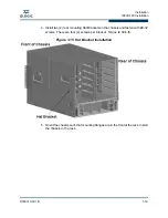
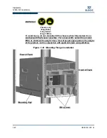
1. Install the hat rails on each side of the switch using three (3) #6-32 screws per
rail. Torque screws to 8in-lb. A typical installation is shown in Figure 1-3. On
the 12300, hat rails are installed with mounting ears towards the power supply
side of the switch. On the 12200, hat rails are installed with mounting ears
towards the port side of the switch.
Figure 1-3 12200 and 12300 Hat Rails
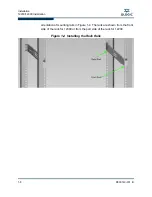
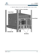
2. Install eight (8) cage nuts into rack posts, two (2) cage nuts per post. Install the
mounting rails and fasten to cage nuts using six (6) M6 screws. Torque screws
to 30in-lb. Do not install two (2) screws in lower locations on equipment
installation side of the rack until the switch is installed in the rack. Note the
Summary of Contents for QLogic 12000 Series
Page 1: ...D000140 001 B QLogic 12000 Hardware Installation Guide...
Page 92: ...QLogic 12000 Series Product Specifications 12800 Series A 8 D000140 001 B S Notes...
Page 97: ...Safety and Regulatory Compliance Information Safety Information D000140 001 B 5 A 2...
Page 109: ...Safety and Regulatory Compliance Information Safety Information D000140 001 B 17 A...
Page 110: ...Safety and Regulatory Compliance Information Safety Information B 18 D000140 001 S Notes...
Page 113: ...Serial Port Pinouts D000140 001 B C 3 A...
Page 114: ...Serial Port Pinouts C 4 D000140 001 B S Notes...
Page 125: ......