QD1 IO Expansion Module User Manual
4 Document Version V3.0 (2020-08-18)
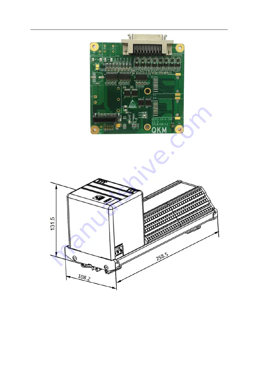
Figure 1-7 Daughterboard of economical QD1
1.2 Product dimensions
1.2.1 Modular type
Figure 1-8 Dimensions of modular QD1 (32 In/32 Out) (unit: mm)
Page 1: ......
Page 2: ...User Manual QD1 IO Expansion Module Modular Economical QKM Technology Dongguan Co Ltd Document Version V3 1 0 Issue Date 18 08 2020...
Page 3: ...gs The signs in this document clearly indicate any dangers warnings attentions and descriptions that may occur while users perform the operations described in this manual be sure to pay attention to t...
Page 4: ...nology Dongguan Co Ltd QKM has been granted ownership of this trademark Disclaimer QKM does not assume any direct indirect special or incidental loss or liability due to improper use of this manual or...
Page 5: ...The version history contains the accumulated information on each update of the document and the latest version of the document includes the updates in all previous versions of the document Version Da...
Page 6: ......
Page 7: ...1 2 2 Economical type 5 1 3 Technical parameters 6 1 3 1 Electrical parameters 6 1 3 2 Dimension parameters 6 1 3 3 Installation environment 7 1 4 Product features 7 Chapter 2 Work Principle 8 2 1 Co...
Page 8: ...20 3 3 1 Installation of motherboard 20 3 3 2 Installation of daughterboards 21 3 3 3 Installation of communication cable 22 3 3 4 Installation of power wire 24 3 4 Check after installation 25 Chapte...
Page 9: ...Contents Document Version V3 1 0 2020 08 18 VII 4 4 Dynamic library configuration 47 Appendix A FAQ 49...
Page 10: ...terms in this manual are described as follows Term Description QKM Quotient Kinematics Machine QD1 QKM Digital Input and Output GDE Guidance Development Environment IO Input output DI Digital intput...
Page 11: ...n the industry Main controller can access and control each IO channel upon connection to QD1 with network cable QD1 module has dual RJ45 network ports with native routing and forwarding function and c...
Page 12: ...roduction of components 1 1 1 Modular type The components of modular QD1 are detailed in Figure 1 4 Modular QD1 16 In 16 Out has the same power interface and network ports as modular QD1 32 In 32 Out...
Page 13: ...of modular QD1 32 In 32 Out 1 1 2 Economical type Economical QD1 consists of a motherboard and a daughterboard with components detailed in Figure 1 6 and Figure 1 7 Figure 1 6 Motherboard of economica...
Page 14: ...Expansion Module User Manual 4 Document Version V3 0 2020 08 18 Figure 1 7 Daughterboard of economical QD1 1 2 Product dimensions 1 2 1 Modular type Figure 1 8 Dimensions of modular QD1 32 In 32 Out u...
Page 15: ...iew Document Version V3 1 0 2020 08 18 5 Figure 1 9 Dimensions of modular QD1 16 In 16 Out unit mm 1 2 2 Economical type Figure 1 10 Dimensions of QD1 motherboard unit mm Figure 1 11 Dimensions of QD1...
Page 16: ...Input channel 32 Input 16 Input 16 Input up to 128 Input Output channel 32 Output 16 Output 16 Output up to 128 Output Input mode Default NPN Customized PNP Default NPN Customized PNP Input signal 0...
Page 17: ...ascading topology Stable and reliable with IO channels completely isolated from the system strong resistance to interference power protection and IO LEDs High integration small size with high integrat...
Page 18: ...bit and users can only read its status but cannot modify it DO is a coil output in which each address corresponds to one data bit and users can set reset and read back its status 2 1 Communication net...
Page 19: ...Document Version V3 1 0 2020 08 18 9 2 1 1 Modular type Figure 2 1 Modular QD1 networking diagram 2 1 2 Economical type Figure 2 2 Economical QD1 networking diagram 16 or 32 channel DO 16 or 32 channe...
Page 20: ...Module User Manual 10 Document Version V3 0 2020 08 18 2 2 Definition of IO pins 2 2 1 Modular type Figure 2 3 Modular QD1 interfaces of 32 In 32 Out top view Figure 2 4 Modular QD1 interfaces of 16 I...
Page 21: ...V GND Digital signal input expansion 01 32 24 V power supply Common port 16 In 16 Out DI 00 16 Digital signal input expansion 01 16 DO interface 32 In 32 Out DO 00 32 24 V GND Digital signal output ex...
Page 22: ...t 00 25 DI_10 Input 10 8 DI_01 Input 01 26 DI_11 Input 11 9 DO_00 Output 00 27 DO_07 Output 07 10 DO_01 Output 01 28 DO_06 Output 06 11 DO_02 Output 02 29 DO_05 Output 05 12 DO_03 Output 03 30 DO_04 O...
Page 23: ...ircuit diagram is shown in Figure 2 6 Figure 2 6 Input circuit diagram of modular QD1 2 3 2 Economical type Economical QD1 supports 16 channel optocoupler isolated digital input and a single slave sta...
Page 24: ...Each channel has a rated output current of 200 mA and the output circuit diagram is shown in Figure 2 8 Figure 2 8 Output circuit diagram of modular QD1 2 4 2 Economical type Economical QD1 supports...
Page 25: ...rated output current of 200 mA and the output circuit diagram is shown in Figure 2 9 Figure 2 9 Output circuit diagram of economical QD1 2 5 Description of LEDs 2 5 1 Modular QD1 Figure 2 10 Modular Q...
Page 26: ...s normally Communication LED LAN1 LAN2 Green Communication LED NO indicates that a communication connection has been established Flashing indicates communication is being performed 100 Mbit s Yellow N...
Page 27: ...D NO indicates the module fails LED4 Red Network LED NO indicates there is a conflict or serious error in IP address Flashing indicates network connection timeout Communication port LAN1 LAN2 Green Co...
Page 28: ...orm installation and ensure that no conductors or other conductive objects fall into PCB during QD1 installation 3 2 Installation of modular QD1 3 2 1 Installation of guide rail Step 1 Install the fix...
Page 29: ...to configuration scenario and with reference to Section 2 1 Communication networking This diagram only presents one example scenario for reference Step 2 Installation of IO signal wires 1 Use a screwd...
Page 30: ...erface and hold it Step 2 Connect the DC power wire to the power interface of QD1 Step 3 Release the power interface and check whether the connection is firm as shown in Figure 3 4 Figure 3 4 Installa...
Page 31: ...ughterboards Upon expansion it supports 32 48 64 112 IO channels which can flexibly meet users requirements Step 1 Install screws and bolts in the mounting holes at the four corners of daughterboard S...
Page 32: ...ependently powered with a total output current of 3 2 A for 16 channels per daughterboard and the motherboard does not provide this output via SCSI interface up to 6 daughterboards can be installed an...
Page 33: ...es 1 Optional step View the definition of pins in Section 2 2 2 Produce an IO connector as shown in Figure 3 9 Figure 3 9 Production of IO connector If the QD1 product you choose to buy is not equippe...
Page 34: ...ircuit will not work or even circuit board will be burnt If many loads are connected or power consumption is large external power supply can be separately provided for loads but common GND terminals n...
Page 35: ...ative poles are connected in reverse Conduct measurement to ensure there is no short circuit before turning on the power Check whether signal wires are connected properly and firmly Check whether fore...
Page 36: ...f QKM 4 1 Initialization configuration 4 1 1 IP address configuration Step 1 Connect QD1 to 24 V d c power supply If the power LED is always on it indicates that power is normally supplied to the modu...
Page 37: ...Settings button to make configuration changes as shown below and click the OK button Then click the Scan button again Figure 4 3 Scan IP address Step 4 Double click the address under IP address bar t...
Page 38: ...ddress is the address set by the user it means that the setting is successful if it fails check whether the set IP address is occupied by another device 4 2 Configuration for connection to robot Prere...
Page 39: ...ontroller in the address bar If network connection is normal click to enter the interface as shown in Figure 4 6 Figure 4 6 Open Web Server Step 2 Open Administrator Control Panel and Teaching Panel i...
Page 40: ...before every change of Data ID 583 value otherwise the Data ID 583 value that is already in effect cannot be modified When the number of IO channels extended for QD1 exceeds 64 repeat Step 2 Step 3 to...
Page 41: ...The first input channel mapped to controller with an initial value of I 10101 5 The first input channel at the beginning of Output with an initial value of 1 6 The last input channel at the end of Ou...
Page 42: ...o 0 Step 2 Set other output ports in sequence according to the examples above 4 3 Configuration for connection to PC Prerequisites Visual Studio 2015 installed on computer personnel familiar with Visu...
Page 43: ...m interface of Windows Sockets example example program include header files that program needs to include library library functions of Modbus protocol Load dll files to C Windows System32 before confi...
Page 44: ...gure 4 11 Open Visual Studio It may not open Win32 Console Application based on Win10 system if you open Visual Studio 2015 directly via the icon Please follow the step to run VS 2015 Step 3 Create a...
Page 45: ...allation Document Version V3 1 0 2020 08 18 35 Figure 4 12 Open Visual Studio 2 Click Visual C in the New Project page and select Win32 Console Application then modify the project name and click OK as...
Page 46: ...QD1 IO Expansion Module User Manual 36 Document Version V3 0 2020 08 18 Figure 4 13 Create Win32 Console Application...
Page 47: ...nsole Application and uncheck empty project as shown in Figure 4 14 Figure 4 14 Application Settings If select empty project you might not find the directory of C in property pages Step 4 Add paths to...
Page 48: ...sion Module User Manual 38 Document Version V3 0 2020 08 18 Figure 4 15 Add paths to include files 2 Select all platforms Figure 4 16 Select platforms 3 Then go back to property pages click VC Directo...
Page 49: ...lude files After adding paths to include files it will be shown in directory page Figure 4 17 Add a path to include files 4 Go back to the property pages click VC Directories Library Directories and E...
Page 50: ...n click the directory of C C General Additional Include Directories and Edit in sequence select paths to additional include files and confirm as shown in Figure 4 19 Figure 4 19 Add a path to addition...
Page 51: ...Document Version V3 1 0 2020 08 18 41 Step 6 Click Linker General Additional Library Directories Edit in sequence select paths to additional library files as shown in Figure 4 21 Figure 4 21 Add a pa...
Page 52: ...odule User Manual 42 Document Version V3 0 2020 08 18 Step 7 Click Linker Input Additional Dependencies and Edit in sequence Fill in modbus lib click OK and Apply as shown in Figure 4 22 Figure 4 22 F...
Page 53: ...ally there are two debug directories under VS projects To run or debug the program through VS you need to place dependent dlls in debug2 and it is ineffective to place them in debug1 For example in de...
Page 54: ...interface Each modbus slave device has its own independent ID which is called slave ID and is an integer Therefore you need to use the modbus_set_slave function to set slave ID for modbus_t structure...
Page 55: ...he read value into the array pointed to by the dest pointer This function returns 0 on success and 1 on failure Example ret modbus_read_input_bits ctx MODBUS_DISCRETE_ADDR MO DBUS_DISCRETE_LEN bits if...
Page 56: ...TRUE if ret 0 fprintf stderr s n modbus_strerror errno int modbus_write_bits modbus_t ctx int addr int nb const uint8_t src Write multiple coils with function code of 0x0F Write the array pointed to...
Page 57: ...s TCP and enter the low power mode After QD1 enters the low power mode if interaction needs to be continued re establish a Modbus TCP connection for the master station if connection needs to be kept a...
Page 58: ...ows h include process h include modbus h This can be any input just to keep connection alive define HEART_BEAT_BIT0 define HEART_BEAT_RATE30000 30s unsigned __stdcall HeartBeat void pParam create the...
Page 59: ...wn functions here Free the connection and disable the thread modbus_close ctx modbus_free ctx CloseHandle hThread return 0 When adding the heartbeat package function please pay attention to the follow...
Page 60: ......
Page 61: ...or controlling channels after normal connection A1 Confirm whether the electrical connection of corresponding channel is normal and whether the connection is loose or dropped A2 Confirm whether the c...
Page 62: ...the configured IP address to ensure that the IP addresses of robot and QD1 are on the same network segment A2 Check whether the value of Date ID 582 in Setup Parameter Database Controller Modbus TCP...
Page 63: ......
Page 64: ......