12
INSTALLATION AND OPERATION MANUAL FOR FLAT ROOF SYSTEM Q.FLAT-G6 – Q CELLS
NOTE:
The location and position of the USO connection
O
4
can be found in the current project report and is only indicative. The
exact position must be determined on site, as it depends on the course of the underlying roof structure.
4
ASSEMBLY
4.5 OPTIONAL STEP
4.5.1 ASSEMBLY OF THE USO CONNECTION O
4
To secure the position against a thermally induced "bead effect", the system can be structurally fastened to the roof in conjunction
with the USO connection
O
4
. In addition, the USO connection
O
4
can be placed instead of ballast blocks in order to keep the
system weight and the additional load on the roof as low as possible.
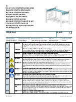
INFO
i
Pre-installed
mounting foot
Positioning and
fastening of the USO
connection on the
mounting foot
Screwing the USO con-
nection to the cross brace
and ballast braces, with
three self-drilling screws
on each side.
Fixing of the cross and
ballast struts according
to specification
Final installed USO
connection
PROCEDURE:
Ideally, the attachment points of the USO connection are mounted / installed before the system is mounted on the roof, but at the latest
before the cross braces and ballast braces
F
are mounted.
The attachment point should be positioned as centrally as possible between the four surrounding towers
E
.
A flat nut and a serrated lock washer are screwed onto the threaded bolt of the attachment point. The serrated lock washer will later
serve as a support for the USO connection
O
4
. The USO connection
O
4
is then pushed over the threaded bolt as centrally as possible.
The lugs are directed upwards and rest against the two cross brace and ballast braces
F
. The tie-in point is then secured with a washer
and a locknut from above and secured with the flat nut from below. Flat nut, serrated lock washer, washer and locking nut are included in
the scope of delivery. To attach the tie-in point to the system, three supplied self-drilling screws per side are screwed through the USO
connection
O
4
into the cross braces and ballast braces
F
.