background image

Pro Video Instruments 


VeCOAX MicroMod 3 AV + HDMI RF Modulator Manual 

16 


ON BOARD DISPLAY - ADVANCED MENU  


These are the Defaults and Good 
starting point for 

PLUG N PLAY


setup.  

Please do not modify these settings 
unless instructed or you understand 
these settings.  

If you require a specific PID set by 
your Service provider for Coax STB 
injection, then please change as per 
their requirements. 

Changing these numbers can create 
unwanted effects on your channel if 
not careful.   


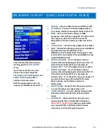
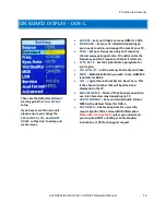
TS ID 

 Transport ID Number. Used for Identification 

of the Mpeg Transport Stream. Default 1  


SERVICE ID


 Also known as the Program ID  


CVCT MODE


 Allows the changing of the VCT Mode 

for TV tuners that have trouble registering the 
assigned Major Minor channel and short name. This 
option only shows in J.83B standard  


PMT


 Program Mapping Table Identification 

Number. Metadata of the MPEG transport stream. 
Contains the PIDS. Default 32  


VIDEO PID


 Identification number for the Mpeg 

Video transport stream. Default is 48  


PCR PID


 Program Clock rate PID. Required to be 

the same number as Video PID to ensure the Video 

and Encoder PID’s are synced correctly and Identified 

in the Transport stream. 


AUDIO PID


 Identification number for the Mpeg 

Audio in the transport stream. Default is 49 


1080P CONV

 This option will downscale 1080P 

video to 1080i automatically when in interlace mode. 
If you switch to Auto mode, the unit will not 
downscale 1080P video and pass through the 
resolution to your tv. Use to support TV tuners that 

don’t support 1080P vide

o.  


RF ATTEN


 Built-in signal attenuation (reduction).  

Reduces signal strength by up to 30 dB. 


MIXER MODE


 Compatibility mode for older tuners 

that still use DVB ATSC 1.0. If you are having issues 
with certain TVs not picking up the channel, please 
try the Alternate mode.  


FIXED EDID 


Set to force video resolution via HDMI 

from source device.  HDMI only.  By default, the unit 
accepts the resolution from the source device (Auto). 


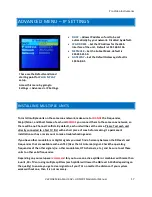
IP SETTINGS - 

Set the IP Address of Web Interface 

and other settings.  (See Page 17). 


RESET - 

Restore unit to factory settings. 

Terms:  

PID = 

(Packet Identifier) 

CVCT = 

(Cable Virtual Channel Table) 


Summary of Contents for VeCOAX MicroMod 3

Page 1: ...VECOAX MICROMOD 3 AV HDMI RF MODULATOR MANUAL ...

Page 2: ...rks with most TV brands including Samsung Sony Vizio LG and More Receives on TVs as its own HDTV channel as a FULL HD signal Up to 1080P with Dolby Digital Audio AC3 Easy Plug and Play Setup with customization options available in the easy to use menu via onboard Color Display and or Web Interface Works With any HD Video HDMI source or Composite Video Source CVBS 720P or 1080P I Fixed Resolution C...

Page 3: ...roubleshooting easier To test your unit simply connect your TV with a short piece of Coax cable to the RF out of the Unit No HDMI needs to be connected for this test Scan for channels on the connected TV Depending on your supported TV standards scan for digital channels After the scan is complete you can tune to channel 1 1 and the test pattern will be visible By default our unit is set to QAM J 8...

Page 4: ...UT 1 On Board Menu Display 7 Analog Stereo Audio Input 2 BLUE On Air Indicator Light 8 HDMI Input 3 RED Power Indicator Light 9 DC 12V Power In 4 Menu Navigation Keys 10 USB PC Port 5 RF In RF Out 11 3 Pin Upgrade Port 6 Composite Video Closed Caption 12 Web Management Port Ethernet ...

Page 5: ...r adapter into the unit After a few seconds the Power LED and On Air LED will both be steady lit 2 Connect a short piece of coax cable to your TV s RF In and the other end to the unit s RF Out 3 Auto Scan for Channels on your TV If prompted for signal type select Digital Cable 4 Once the scan is complete tune to the Channel found on your TV You should see a PVI test pattern screen 5 Connect your H...

Page 6: ...col Version 4 TCP IPv4 and click on Properties 6 In the Properties select Use the following IP address and set the static IP 192 168 0 100 7 Click OK You are now ready to connect See WEB INTERFACE CONFIGURATION GUIDE on Page 6 for details NETWORK CONNECTION VIA MAC OS X These steps walk you through setting a Mac running OS X to a Static IP address to allow an Ethernet connection with the unit on i...

Page 7: ...admin Once you have logged into the unit you will see the SETTINGS page This will display all your inputs as well as your video standard frequency and other settings On the left hand side there is a navigation bar where you can select different menus for further configuration SETTINGS Here you can change your broadcast settings for each channel of your unit including the broadcast standard and fre...

Page 8: ...s for certain formats such as J 83B DVB T and ISDB T MAJOR First number of the digital channel i e for channel 1 3 1 is the Major MINOR Second number of the digital channel i e for channel 1 3 3 is the Minor SHORT NAME Name of the channel e g ESPN DVD FOX etc AUDIO FORMAT Change the audio format of the channel AC3 is recommended for USA Canada Mexico Please ensure your HDMI source is set to Stereo...

Page 9: ...you have issues where your HDMI source is not being detected by the unit then set this option to the desired resolution supported by your HDMI source e g 1080 1080i 720p This sends a command to the HDMI source that the only support resolution is the valve set in this option This forces the resolution to be stuck in the set value and may not change Click APPLY to lock in changes NETWORK TAB ONLY CH...

Page 10: ... this to match your current network settings Click APPLY to lock in changes If the IP Address etc is changed be sure to use the new IP Address to access the unit s web interface UPDATE TAB Provides the interface for unit Firmware updates ONLY USE AS DIRECTED BY PVI SUPPORT STAFF ABOUT TAB Provides Firmware Version information ...

Page 11: ...efault and works with 99 of TVs QAM256 is used in applications that require it such as with other coax systems that use QAM256 or only support QAM256 mode MAJOR CHANNEL This is the Major channel number that will be displayed and stored in the TV s Virtual Channel Table VCT For example for channel 10 1 10 is the Major channel number MINOR CHANNEL This is the Major channel number that will be displa...

Page 12: ...QUALITY Set the Latency Mode of your Video MAJOR CHANNEL This is the Major channel number that will be displayed and stored in the TV s Virtual Channel Table VCT For example for channel 10 1 10 is the Major channel number MINOR CHANNEL This is the Major channel number that will be displayed and stored in the TV s Virtual Channel Table VCT For example for channel 10 2 2 is the Minor channel number ...

Page 13: ...hannel it relates to VID QUALITY Set the Latency Mode of your Video MOD Modulation Mode you wish to use QAM64 is the default and works with 99 of TVs QAM256 is used in applications that require it such as with other coax systems that use QAM256 or only support QAM256 mode LCN Logical channel number can be set here This is the channel number that will be stored and displayed on the TV SERVICE NAME ...

Page 14: ...he Frequency and the Frequency Channel it relates to SYM RATE Set the Symbol Rate appropriate for your region VID QUALITY Set the Latency Mode of your Video MOD Modulation Mode you wish to use QAM256 is default for DVB C LCN Logical channel number can be set here This is the channel number that will be stored and displayed on the TV SERVICE NAME Name of the Channel you wish to use 4 6 Characters m...

Page 15: ... your TV FREQ Set your Frequency using our Frequency chart at www pvisupport com TVs will scan for the Frequency and the Frequency Channel it relates to VID QUALITY Set the Latency Mode of your Video KEY ID Set your Key ID channel number SERVICE NAME Name of the Channel you wish to use 4 6 Characters max depending on TV AUDIO FORMAT Set your desired Audio Format AAC is the default standard for ISD...

Page 16: ...s please search for these online to determine the Frequencies available for your region VID QUALITY Set the Latency Mode of your Video MODE Modulation mode can be set here depending on your needs for your region LCN Logical channel number can be set here This is the channel number that will be stored and displayed on the TV SERVICE NAME Name of the Channel you wish to use 4 6 Characters max depend...

Page 17: ...transport stream Default is 48 PCR PID Program Clock rate PID Required to be the same number as Video PID to ensure the Video and Encoder PID s are synced correctly and Identified in the Transport stream AUDIO PID Identification number for the Mpeg Audio in the transport stream Default is 49 1080P CONV This option will downscale 1080P video to 1080i automatically when in interlace mode If you swit...

Page 18: ... there will be no Channel Conflicts By default each unit will be set the same Please Test each unit directly connected to a Test TV first with a short piece of coax before making it a permanent installation such as a rack mount to make troubleshooting easier If you have other modulators or Digital signals you must find a harmony between the RF levels and Frequencies that are available such as ATSC...

Page 19: ...service provider of your basic cable to find the frequencies that they use and find the ones that are available for you to use If you wish to inject into a Digital Cable Converter box or STB set top box most of the time the service provider will include a channel you may broadcast onto or some providers require a specific PIDs to be set which can be set in the ADVANCED OPTIONS MENU in order for th...

Page 20: ... s menu ATSC corresponds to Over the Air J83B is QAM Digital cable etc FOR DEFAULT SETTINGS set TV to scan for Auto or Cable In rare cases some TVs may not be able to display the test pattern Rule this out by connecting a dumb HDMI signal source e g DVD player then scan for channels on the TV Test with another TV to rule out TV issue if possible If TEST PATTERN works but there is NO VIDEO from int...

Page 21: ...If the source is a computer set Display to Extended mode or Extend these displays and set to 1920x1080 or 1280x720 On the unit go to Advanced Options Fixed EDID setting and change from Auto to match the fixed resolution setting on the source For instance if the source is set to 1080p Fixed change Fixed EDID to 1080p Change Video Quality on the unit from Low Latency to Average or High If STANDARD i...

Page 22: ...ernet patch cable If connecting directly to your computer check that your computer is set to a static IP address in the same network segment as the unit See page 5 for direction on how to set a static IP address Check the On Board menu Settings Advanced IP Settings to verify you are using the correct address Reset the unit to default settings by pressing the Enter and Escape keys simultaneously an...

Page 23: ...r Minor settings and make sure they do not match any other equipment in the network The unit s signal output may oversaturate other signals on the network To attenuate the signal from the unit in the menu go to Advanced Options RF Attenuator then change from 0db in 5db to 10db increments and retest Also consider amplifying the other signals in the network to achieve ideal balance NOT ALL OF MY TVS...

Page 24: ...RENT STANDARDS This refers to the broadcast standard of the RF output North American standards are J 83B digital QAM Cable and ATSC digital over the air antenna International broadcast standards supported include DVB T DVB C ISDBT and DTMB Be sure to use a standard that is compatible with your TV and region WHAT IS THE ADVANCED OPTIONS MENU The Advanced Options Menu allows adjustments of PSIP and ...

Page 25: ...the coax cable it slowly becomes attenuated which results in the other TVs not having this issue To combat this please add an inline digital attenuator or use the Advanced Options RF Attenuator option WHAT IS EDID Extended Display Identification Data EDID is a metadata format for display devices to describe their capabilities to a video source e g graphics card or set top box It is the Basic HDMI ...

Page 26: ... Minor to match For example 195 000Mhz QAM is physical channel 10 So we set the Major Minor to 10 1 Each digital cable channel must have a Major and Minor So all Channels will display its Major and Minor number 10 1 11 1 12 1 13 1 etc TECH SUPPORT CONTACT US Before contacting us please read this manual carefully as it covers ALL and EVERY aspect to set this product as per your needs using pictures...

Page 27: ... MHz Apart Note this is just the frequency the VeCOAX will use on the coax cable spectrum IT IS NOT the memory position number on the TV You can set ANY memory position number on the TV by setting the Major Minor Number as you prefer EXAMPLE 1 1 so it will go to the button number 1 on the TV remote Channel Number QAM CDSREF Carrier MHz Subband T Channels 6 MHz Apart Lowband 2 57 00 3 63 00 4 69 00...

Page 28: ... VeCOAX MicroMod 3 AV HDMI RF Modulator Manual 27 96 99 00 97 105 00 98 111 00 99 117 00 Midband 14 123 00 15 129 00 16 135 00 17 141 00 18 147 00 19 153 00 20 159 00 21 165 00 22 171 00 Highband 7 177 00 8 183 00 9 189 00 ...

Page 29: ...COAX MicroMod 3 AV HDMI RF Modulator Manual 28 10 195 00 11 201 00 12 207 00 13 213 00 Superband 23 219 00 24 225 00 25 231 00 26 237 00 27 243 00 28 249 00 29 255 00 30 261 00 31 267 00 32 273 00 33 279 00 34 285 00 35 291 00 ...

Page 30: ...COAX MicroMod 3 AV HDMI RF Modulator Manual 29 36 297 00 Hyperband 37 303 00 38 309 00 39 315 00 40 321 00 41 327 00 42 333 00 43 339 00 44 345 00 45 351 00 46 357 00 47 363 00 48 369 00 49 375 00 50 381 00 51 387 00 52 393 00 ...

Page 31: ...COAX MicroMod 3 AV HDMI RF Modulator Manual 30 53 399 00 54 405 00 55 411 00 56 417 00 57 423 00 58 429 00 59 435 00 60 441 00 61 447 00 62 453 00 63 459 00 64 465 00 Ultraband 65 471 00 66 477 00 67 483 00 68 489 00 69 495 00 ...

Page 32: ...COAX MicroMod 3 AV HDMI RF Modulator Manual 31 70 501 00 71 507 00 72 513 00 73 519 00 74 525 00 75 531 00 76 537 00 77 543 00 78 549 00 79 555 00 80 561 00 81 567 00 82 573 00 83 579 00 84 585 00 85 591 00 86 597 00 87 603 00 ...

Page 33: ...MicroMod 3 AV HDMI RF Modulator Manual 32 88 609 00 89 615 00 90 621 00 91 627 00 92 633 00 93 639 00 94 645 00 Jumboband 100 651 00 101 657 00 102 663 00 103 669 00 104 675 00 105 681 00 106 687 00 107 693 00 108 699 00 109 705 00 ...

Page 34: ...oMod 3 AV HDMI RF Modulator Manual 33 110 711 00 111 717 00 112 723 00 113 729 00 114 735 00 115 741 00 116 747 00 117 753 00 118 759 00 119 765 00 120 771 00 121 777 00 122 783 00 123 789 00 124 795 00 125 801 00 126 807 00 127 813 00 ...

Page 35: ...oMod 3 AV HDMI RF Modulator Manual 34 128 819 00 129 825 00 130 831 00 131 837 00 132 843 00 133 849 00 134 855 00 135 861 00 136 867 00 137 873 00 138 879 00 139 885 00 140 891 00 141 897 00 142 903 00 143 909 00 144 915 00 145 921 00 ...

Page 36: ...deo Instruments VeCOAX MicroMod 3 AV HDMI RF Modulator Manual 35 146 927 00 147 933 00 148 939 00 149 945 00 150 951 00 151 957 00 152 963 00 153 969 00 154 975 00 155 981 00 156 987 00 157 993 00 158 999 00 ...

Page 37: ...ote this is just the frequency the VeCOAX will use on the coax cable IT IS NOT the memory position number on the TV You can set ANY memory position number on the TV by setting the Major Minor Number as you prefer EXAMPLE 1 1 so it will go to the button number 1 on the TV remote frequencies in MHz 6 MHz Apart Channel ATSC FREQUENCY 2 57 3 63 4 69 5 79 6 85 VHF high band band III Channel ATSC FREQUE...

Page 38: ...croMod 3 AV HDMI RF Modulator Manual 37 13 213 UHF band Channel ATSC FREQUENCY 14 473 15 479 16 485 17 491 18 497 19 503 20 509 21 515 22 521 23 527 24 533 25 539 26 545 27 551 28 557 29 563 30 569 31 575 32 581 33 587 34 593 35 599 ...

Page 39: ...icroMod 3 AV HDMI RF Modulator Manual 38 36 605 37 611 38 617 39 623 40 629 41 635 42 641 43 647 44 653 45 659 46 665 47 671 48 677 49 683 50 689 51 692 Channel ATSC FREQUENCY 52 701 53 707 54 713 55 719 56 725 57 731 58 737 59 743 ...

Page 40: ...icroMod 3 AV HDMI RF Modulator Manual 39 60 749 61 755 62 761 63 767 64 773 65 779 66 785 67 791 68 797 69 803 Channel ATSC FREQUENCY 70 809 71 815 72 821 73 827 74 833 75 839 76 845 77 851 78 857 79 863 80 869 81 875 82 881 83 887 ...

Page 41: ...SUGGESTED DEFAULT 473142KHZ 473 142 MHz freq channel 14 frequencies in kHz 6 MHz Apart Channel ISDBT FREQUENCY 14 473142 15 479142 16 485142 17 491142 18 497142 19 503142 20 509142 21 515142 22 521142 23 527142 24 533142 25 539142 26 545142 27 551142 28 557142 29 563142 30 569142 31 575142 32 581142 33 587142 ...

Page 42: ... Manual 41 34 593142 35 599142 36 605142 37 NOT USED 38 617142 39 623142 40 629142 41 635142 42 641142 43 647142 44 653142 45 659142 46 665142 47 671142 48 677142 49 683142 50 689142 51 695142 52 701142 53 707142 54 713142 55 719142 56 725142 57 731142 58 737142 ...

Page 43: ...755142 62 761142 63 767142 64 773142 65 779142 66 785142 67 791142 68 797142 69 803142 DVB T CHANNELS APPENDIX Please download the DVB T additional PDF for your country available on our Tech Support Website pvisupport com EUROPE NEW ZEALAND 8 MHz band AUSTRALIA 7 MHz Band COLOMBIA 6 MHz Band END ...

Reviews: