background image

CONQUEST

® 

WATER HEATER


53 

PV500-71   02/16


18.2  LED Error Code Listing 

The following table lists the errors detected by the Platform Ignition Module (PIM) control and the 
associated LED indications. 


Error Mode


LED Code


Recommended Troubleshooting


Normal Operation 

Off 


ID Card Fault 

Red LED Steady ON, 

Green Power LED OFF 

Check that the proper ID card is securely connected. 
Perform a power and system reset. 

Internal Control 

Failure 

Steady ON 

Perform a power and system reset. If fault remains, 
replace the PIM. 

Airflow Fault 

1 flash 

Check Blower operation and airflow switch. 

False Flame Error 

2 flashes 

Check for proper gas valve closure. Clean burner and 
electrodes. 

Ignition Lockout Fault 

3 flashes 

Check the gas supply. See Table 6-1 for more 
information. 

Ignition Proving 

Current Fault 

4 flashes 

Check HSI element. Replace with a new element of 
the proper rating. 

Low Voltage Fault 

5 flashes 

Check the 24 VAC input voltage. The voltage must be 
above 18.0 VAC 

Vent Temperature 

Fault 

6 flashes 

Check for a blocked flue. Check the vent sensor and 
connections. 

Hi-Limit Fault 

7 flashes 

Check for proper water flow. Check hi-limit and outlet 
sensors. 

Sensor Fault 

8 flashes 

See the digital control display for fault identification. 
Check sensors and wiring. 

Safety #1 Fault 

9 flashes 

Check gas pressure. Verify proper safety switch 
operation. 

Water Pressure Fault 

10 flashes 

Check piping for leaks. Check pressure switch and 
connections. 

Blower Speed Fault 

11 flashes 

Verify tachometer signal and connection on J5. 

LWCO Fault 

12 flashes 

Check LWCO switch and connections. Check the 
water level. 

Hi-Temperature Delta 

Fault 

13 flashes 

Check pump operation. Confirm proper water flow 
across heat exchanger. 

Ft-bus 

Communications 

Fault 

14 flashes 

Verify the digital control display is connected and 
operating. Check the cable between the control display 
and J1. 

Safety #2 Fault 

15 flashes 

Check gas pressure. Verify proper safety switch 
operation. 


Summary of Contents for conquest 40 L 130 A-GC

Page 1: ...NANCE OF THIS EQUIPMENT READ AND FOLLOW THE INFORMATION IN THIS MANUAL AND ALL OTHER PROVIDED INSTRUCTIONS LABELS AND MARKINGS BEFORE INSTALLING OPERATING OR SERVICING THIS UNIT TO THE INSTALLER After installation these instructions must be given to the equipment user or left near the appliance SPECIAL INSTRUCTIONS TO THE OWNER Retain this manual for future reference These instructions contain imp...

Page 2: ...trol Trains 6 3 Inlet Pressure 6 4 Manifold Pressure 6 5 Gas Piping Size 6 6 Appliance Isolation During Gas Supply Piping Pressure Test 6 7 Gas Connection 7 Combustion and Ventilation Air 7 1 Equipment Located in Confined Spaces 7 2 Maximum Allowed Remote Combustion Air Inlet Length 7 3 Remote Combustion Air Cap 7 4 Vertical or Horizontal Remote Air Duct Termination 7 5 Combining Remote Air Ductin...

Page 3: ... 12 1 EOS register List 12 2 Error Codes 13 Remote Connections Terminal Strip 13 1 Making BMS BAS Remote Connection for Analog and Binary Signals 13 2 Terminal Functions 14 Sequence of Operation 15 Initial Startup 15 1 Initial Startup Requirements 15 2 Tools and Instrumentation Required 15 3 Resources 15 4 On Site Considerations 15 5 Pre Startup Checklist 15 6 Startup Procedure 16 Potentiometer Op...

Page 4: ...MES FOR THE PHYSICALLY HANDICAPPED HOSPITALS AND NURSING HOMES ELDER CARE FACILITIES AND REST HOMES ORPHANAGES AND CHILD CARE FACILITIES OTHER INSTALLATIONS WHERE RESPONSE TO CONTACT WITH HOT WATER MAY BE SLOWER OR WHERE THE DANGER OF HOT WATER CONTACT IS GREATER Thermostatically controlled mixing valves must be used in the design of the potable hot water system Potable hot water should be tempere...

Page 5: ...ains or may come to contain materials that have been identified as carcinogenic or possibly carcinogenic to humans Before installing servicing or removing this product read and follow the supplied instructions Clearance in accordance with the local installation codes and the requirements of the gas supplier Dégagement conforme aux codes d installation locaux et aux exigencies du foumisseunde gaz S...

Page 6: ...ontrols Use NIOSH MSHA approved respirators as required see MSDS Wear long sleeved loose fitting clothing eye protection and gloves FIRST AID MEASURES If any of the irritations listed persists seek medical attention Eyes Flush with water Skin Wash with soap and warm water Ingestion Do not induce vomiting Get medical attention if gastrointestinal symptoms develop Inhalation Remove to fresh clean ai...

Page 7: ...CONQUEST WATER HEATER 7 PV500 71 02 16 2 PRODUCT DESCRIPTION Component Controls and Connection Locations Locations May Vary ...

Page 8: ...on of the National Electrical Code ANSI NFPA No 70 In Canada the electrical service must conform to local electrical codes and or CSA C22 1 Canadian Electrical Code Part 1 All wiring between the unit and field installed devices must be made with type T copper wire Line voltage wire exterior to the appliance must be enclosed in approved conduit or approved metal clad cable To avoid serious damage D...

Page 9: ...ing water gas vent combustion air electrical pump and other auxiliary optional equipment and connections 3 7 Other Code and Regulatory Clearances and Requirements Additional clearance beyond the minimum required to combustible materials and other requirements may be required to comply with local state or national codes and regulations It is to the responsibility of the installer to comply with the...

Page 10: ...nquest should not exceed 100ºF It is also recommended that the building return or dishwasher recirculation piping be connected to the return water connection located at the mid tank and not to the cold inlet water supply The Conquest utilizes cold inlet water to help extract almost all of the heat energy from the products of combustion which lowers the vent temperature to allow the use of PVC vent...

Page 11: ...CONQUEST WATER HEATER 11 PV500 71 02 16 SINGLE STORAGE WATER HEATER WITH SUPPLEMENTAL STORAGE TANK TWO WATER HEATERS WITH REVERSE RETURN PIPING ...

Page 12: ...ting allowed by these vent materials Contact factory for instructions 3 Change the following EOS control settings on the Conquest water heater applied as the high temperature water source for a dish washing application a Adjust the operating differential DIFF to 2 F 2 Adjust the operating offset OFFSET to 3 F and 3 If the installed exhaust venting material is solid CPVC or ETL UL ULC or CSA listed...

Page 13: ... polypropylene or stainless steel venting Contact factory for instructions 4 Change the following EOS control settings on the Conquest water heater applied as a booster heater using the required CPVC or ETL UL ULC or CSA listed polypropylene or stainless steel venting system a Adjust the operating differential DIFF to 2 F 2 Adjust the operating offset OFFSET to 3 F and 3 Adjust the vent temperatur...

Page 14: ...d pipe can be added to the condensate drain connection to relocate the condensate trap assembly as long as all added parts are at the same elevation After attachment the trap must be rotated so the offset in the pipe aims down toward the floor Do not rotate the offset toward the ceiling Do not use tools to tighten the PVC union Hand tighten the PVC union to seat the internal gasket 2 Do not combin...

Page 15: ...convenient place between the condensate outlet and a suitable drain and where the 3 threaded end cap can be removed to recharge the Neutralizer with crushed limestone a The CNS must be located such that condensate will flow downhill from the condensate trap outlet to the inlet on one end of the CNS and downhill from the other end of the CHS to the drain If this continuous downhill flow is not main...

Page 16: ...type regulator manual test valve and manifold pressure taps These components may be separate or combined in a common housing WARNING Do not adjust or remove any screws or bolts on gas train control components which are secured with a red or blue sealing compound In addition to voiding warranties and certification listings such adjustment or disassembly can cause improper operation which could resu...

Page 17: ...pliance Isolation during Gas Supply Piping Pressure Test 1 The appliance and its provided manual shutoff valve must be disconnected from the gas supply piping system during any pressure testing of that system at test pressures in excess of PSI 3 5 kPa 2 The appliance must be isolated from the gas supply piping system by closing its individual manual shutoff valve during any pressure testing of the...

Page 18: ...isions for adequate combustion and ventilation air to the mechanical room must be in accordance with Section Air for Combustion and Ventilation in the latest edition of the NFPA 54 National Fuel Gas Code ANSI Z223 1 and or CAN CSA B149 Installation Codes or applicable provisions of the local building codes Any method addressed in NFPA 54 National Fuel Gas Code section Air for Combustion and Ventil...

Page 19: ... The maximum length of field supplied single wall pipe such as galvanized ventilation pipe is shown in the chart below titled Maximum Air Inlet Duct Equivalent Length Use metal tape or RTV sealant to seal each pipe joint Maximum Air Inlet Duct Equivalent Length Max Elbows Duct Size 4 Duct 6 Duct 8 Duct Max Equivalent Length Model 40 125 feet 4 200 feet 10 300 feet 10 Max Equivalent Length Model 50...

Page 20: ...and a combined duct system designed by one of the duct design firms identified at www pvi com vent design html Before operation of a combined remote air ducting system all of the duct design firm s system installation and operation requirements must be in place their instructions followed and the system must be properly maintained Combined Conquest air intake piping must incorporate a variable spe...

Page 21: ...dule or more often based on severity of contamination Inadequate combustion air or non combustible particulate matter such as dust dirt dryer lint concrete dust dry wall dust or the like can be drawn in with combustion air and block burner ports This can cause unreliable operation and non warrantable failures When the optional field installed filter box is required do not operate the appliance wit...

Page 22: ...ht such that rain and products of combustion cannot pass from outdoors back indoors Additional steps required when venting with solid PVC or CPVC pipe 1 Read and follow the information instructions and warnings in VENTING section 2 Do not insulate the plastic vent pipe 3 Design the vent pipe route so that normal expansion pipe getting longer and contraction pipe getting shorter due to on and off t...

Page 23: ... death WARNING Do not vent this water heater into an existing or traditional gas vent or chimney do not combine the vent with any other appliance and do not use a barometric damper in the vent Such venting could result in failure of the venting system and or exposure to carbon monoxide which can result in property damage personal injury or death 8 2 Maximum Vent Length Equivalent Length The maximu...

Page 24: ...d at least 2 feet 0 61 m above the highest point of the roof within a 10 foot 3 05 m radius of the termination 10 A vertical termination less than 10 feet 0 91 m from a parapet wall must be a minimum of 2 feet 0 61 m higher than the parapet wall 8 4 Combining Category IV Vents 1 Combined Conquest Category IV gas vent systems must incorporate an Exhausto Tjernlund or US Draft variable speed modulat...

Page 25: ...C 4 x 36 Each IPEX System 636 vent kit includes or specifies the required pipe fittings hardware adhesives and Installation instructions Follow the IPEX Installation instructions and use only the materials and adhesives it specifies Additional copies of the Installation Guide for the IPEX System 636 concentric vent kit and additional information is available at www ipexinc com or www pvi com vent ...

Page 26: ...ct and vent pipe equivalent lengths provided in this Installation Maintenance Manual Remember to include the IPEX System 636 Concentric Vent Termination Kit in the maximum equivalent calculation When calculating the additional length added by the IPEX kit use the diameter of the IPEX kit combustion air duct connection as the combustion air duct diameter 3 Select a concentric vent kit which matches...

Page 27: ...anywhere between the appliance and the vent termination point such that it is unable to expand or contract as it heats and cools during operation e The weight of the concentric kits must be supported by clamps straps and not by the vent system it connects to f All penetrations must be sealed according to local building codes Caulking for side wall terminations and flashing for roof penetrations ar...

Page 28: ... hazardous materials or death 9 OPERATING AND SAFETY CONTROLS 9 1 Temperature and Pressure Relief Valve s A Temperature and Pressure Relief Valve s sized in accordance with the ASME Boiler and Pressure Vessel Code Section IV HLW is installed in the tank WARNING Secure the relief valve discharge pipe to a suitable floor drain such that very hot water does not openly splash during a significant reli...

Page 29: ...splayed on the controller touch screen This failure lockout can be reset by pressing the LWCO RESET button located on the front control panel Once the LWCO control board has been reset the Main Reset button located on the front control panel can be reset as well The Electronic Low Water Cut Off probe is located in the top head of the water heater WARNING Turn off all electrical service to the appl...

Page 30: ...PIM ID Card Touch Screen User Interface BTC II 10 1 Touch Screen User Interface The touchscreen of the EOS provides one touch access to view and adjust various Menu set points The touchscreen displays Status Fields Items Heater Output and Number Fields It also contains buttons for navigation adjustment and the Home Button to access menu selections Flame current test pins ID card plug J6 Reset Pote...

Page 31: ...low PREP The EOS is Pre Purging the burner system IGN The Hot Surface Igniter is hot and the gas valve has opened to attempt burner ignition 4 seconds BURN The Burner has ignited and the flame has been sensed POST The Call for Heat has ended and the EOS is Post Purging the burner system 10 3 Operational Sequence Field Display The EOS displays the following burner operational sequence ignition stat...

Page 32: ...r located in the flue outlet TANK TOP Displays the current temperature at the top of the water heater tank as measured by the operating control sensor located near the hot outlet TANK BOT Displays the current temperature near the bottom of the water heater tank as measured by the control sensor responsible for regulating the operation of the integral tank circulator TANK T Displays the current tem...

Page 33: ...ours of operation and number of cycles TIME Sets the time day and year Setting the time clock is necessary when using the scheduled setback SCHEDULE Allows the user to create a schedule for reducing the water heater set point when a building is unoccupied for a period of time NETWORK Displays and modifies parameters for creating a Modbus communication connection with the water heater OVERRIDE Allo...

Page 34: ...rating set point for times when a facility is not occupied or the use of hot water is curtailed 1 Press and hold the HOME button for 3 seconds to enter the Control System Menu Use the NEXT ITEM button to scroll to the SCHEDULE MENU Activate the schedule function by first turning on the HEAT SCHD using the arrow buttons 2 There are four setback schedule types 24hr 5 2 5 11 and 7DAY The 24hr schedul...

Page 35: ...IDE MENU and ENTER THE ADVANCED LEVEL ACCESS 1 Press and hold the Home button for 3 seconds 2 Touch the Next Item or Item Back buttons to navigate to the TOOLBOX menu 3 Touch the ENTER button to display the ACCESS screen 4 Depending on the controls software version the ADVANCED level can be selected using the UP and DOWN arrow buttons Subsequent software revisions will require that button 4 in the...

Page 36: ...esired set point displayed in the OPERATOR screen located in the SOURCE control system menu The standalone set point can be adjusted independently of the touchscreen but a specific setting may be difficult to achieve using the temperature index on the PIM See POTENTIOMETER Adjusting the Setpoint 10 11 Using Tool Box Menu The TOOL BOX MENU contains several adjustable parameters as well as up to the...

Page 37: ...a leaky gas valve which propagates a flame after the call for heat cycle has ended Check for leakage through the gas valve If no mechanical cause can be found replace flame control 2 19 FLAME FAIL Flame failure indicates that during the burner ignition process the burner either failed to light or it did light but no flame signal was detected If the burner fails to light it is likely that the hot s...

Page 38: ...ignition failure In this case the lockout may only be reset by the on board manual reset button or the remote reset input condition may be caused by a sensor failure or a faulty control board HTR TOP Indicates a problem with the top temperature sensor possibly a broken or shorted sensor wire or failed sensor NOTE The top sensor and the high limit sensor or located in the same probe body 8 11 HI LI...

Page 39: ...stablished 1 Enter the Network Menu as previously explained The first screen ADDRESS will allow the user to set the network address for each individual heater There are up to 247 addresses beginning with number 1 If there are multiple heaters in the network each heater should have a unique address The default value 1 2 The second screen DATA sets the data format Select between RTU 8bit and ASCI 7b...

Page 40: ...e Read Input S16 F 22 to 266 111 Modulation Rate Read Input U16 0 to 100 112 Flame Current Read Input U16 0 1V 0 10 0 113 Burner Runtime Read Input U16 Hours 0 65535 114 Burner Cycles Read Input U16 Num 0 65535 115 Heater Circulator Status Read Input U16 Enum 0 Off 1 On 116 Heater Setpoint Occupied Read Write Holding S16 F 70 to 190 200 Heater Setpoint Unoccupied Read Write Holding S16 F 70 to 190...

Page 41: ...iler Outlet Tank Top Sensor 12 Boiler Inlet Tank Bottom Sensor 13 Vent Sensor 14 Hi Limit Sensor 15 Ignition Failure 16 Flame Loss 17 Vent Hi Limit 18 Boiler Tank Hi Limit 19 False Flame 20 OEM Card 21 Internal Failure 22 Hi Delta 23 Low HSI 24 Low Voltage 25 Blower Speed 26 High Gas Pressure tN4 Errors This series of errors are related to the communication links between multiple heaters in a link...

Page 42: ...rcuit a relay with gold plated contacts or the use of two relay contacts in parallel must be used Terminals are wired to a relay in a remote Energy Management System When the relay closes the circuit from R1 to R2 is completed and appliance controls are enabled This appliance ships from factory with a jumper between terminals Remove jumper when connecting to a remote controller A1 A2 Used to activ...

Page 43: ...ank thermistor temperature If the two temperatures are not the same a sensor failure will result d When the High Temperature Limit operation has been verified by comparison the limit temperature will then be confirmed to be under the maximum allowable temperature e Terminals P1 P2 are closed to activate any connected remote devices f The circuit between Terminals C1 C2 is closed by any connected r...

Page 44: ...en the main control switch is turned on the control system will continuously monitor the water temperature in the tank and attempt to maintain a uniform water temperature within the tank by using the integral circulating pump b If the temperature sensed in the tank drops 5 degrees or more below the temperature setpoint the pump is energized and a pump circulator icon will illuminate on the control...

Page 45: ...Website www pvi com Technical Support 1 800 433 5654 15 4 On Site Considerations Electrical Supply in accordance with the Nameplate Rating Adequate uncontaminated indoor or outdoor combustion air Adequate Fuel Supply Adequate Water Supply Exhaust Vent that complies with the installation instructions Condensate drainage that complies with the installation instructions 15 5 Pre Startup Checklist Bef...

Page 46: ...tion may occur and may cause a burner lockout To remove this startup condensation after startup is complete and the booster heater storage tank has reached its intended maximum water temperature turn the booster heater off remove the condensation drain plug allow any condensation to drain replace the drain plug and turn the booster water heater on IMPORTANT Using the T P Relief valve alone to vent...

Page 47: ... gas valve tighten the leaking connection then open the manual gas shutoff valve again and check for leaks 9 Now open the 1 8 pilot shut off test valve connected to the manual shutoff gas valve downstream of the gas train closest to the burner and note the gas pressure measured by the monometer Check the gas pressure again after about 15 minutes A gas pressure increase of 0 5 W C or more indicates...

Page 48: ...s in excess of 200 ppm contact PVI Customer Care for assistance WARNING Do not continue to operate the appliance with carbon monoxide levels above 200 ppm Carbon monoxide is a colorless odorless and poisonous gas that commonly results from gas combustion High concentrations of Carbon Monoxide are extremely dangerous to humans and animals Operation of an appliance at carbon monoxide levels above 20...

Page 49: ... BACK buttons to navigate to the HEATER MODULATION HTR MOD menu This setting will override the operating control and using the up or down arrow buttons force the burner to fire at a selected firing rate NOTE If the HTR MOD program is activated while the burner is firing the burner will shut down and recycle i Using the UP or DOWN arrow buttons adjust the firing rate from OFF to the minimum firing ...

Page 50: ...unication between the two devices is interrupted This internal setpoint can be adjusted using the potentiometer to maintain a different operating temperature under these circumstances if desired To Adjust The PIM Potentiometer Setpoint 1 From the View Menu press and hold the HOME button for 3 seconds to display the SETUP Menu 2 Using the NEXT ITEM or ITEM BACK buttons navigate to the TOOLBOX menu ...

Page 51: ...located seperate from food and utensil handling areas When this is not possible in a food service installation the water heater must be sealed to the floor to prevent water from accumulating underneath The floor must be clean smooth and level for adequate sealing Seal the water heater to the floor using an RTV sealant such as Red Devil 0826 Saf T Lok 732 or RTV 102 or an equivalent Follow the seal...

Page 52: ...Check for 120V at the common side of air switch Check if switch tubing is connected on both ends Remote Proving Interlock When terminal C1 and C2 are used a proving circuit for remote equipment failure to close this circuit within the allotted time for Call for Heat will prevent operation and cause an alarm indication Check for proper operation and proving of remote equipment Loose Wire Connection...

Page 53: ...Low Voltage Fault 5 flashes Check the 24 VAC input voltage The voltage must be above 18 0 VAC Vent Temperature Fault 6 flashes Check for a blocked flue Check the vent sensor and connections Hi Limit Fault 7 flashes Check for proper water flow Check hi limit and outlet sensors Sensor Fault 8 flashes See the digital control display for fault identification Check sensors and wiring Safety 1 Fault 9 f...

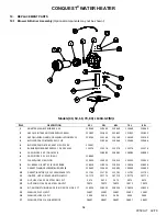
Page 54: ...CE 3 X 2 ID AGC ACB 128985 128985 128985 128985 6 CAP ORIFICE 3 X 1 3 4 ID AGC 128984 7 CLAMP HOSE 1 4 NYLON 120333 120333 120333 120333 120333 8 ELL BRASS 1 8 NPT X 1 4 HOSE BARB 118016 118016 118016 118016 118016 9 GASKET FLANGE BLOWER BURNER 1 8 120493 120493 120493 120493 120493 10 GASKET IGNITOR 1 8 232 CRANEGLAS Y271 111791 111791 111791 111791 111791 11 IGNITER HOT SURFACE NORTON 271Y 10777...

Page 55: ...ERMINAL BLOCK WAGO 280 402 23A 122320 122320 13 SWITCH AIR PROVING CLEVELAND CONTROLS NS2 1166 01 0 50 WC 121444 121444 14 FLAME CONTROL PIM FENWAL 126088 126088 15 TRANSFORMER STEP DOWN TRIAD F5 24 115VAC 24VCT 12 0VA 126865 126865 16 BAR GROUND SQUARE D PK5GTA 5 POLE 122321 122321 17 LWCO PROTODESIGN LW 3 C 1 A 03 120V 113915 113915 18 BOARD TERMINAL ELEC TRON PV13140 10 POLE FEED THRU TYPE 1225...

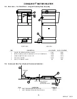
Page 56: ... PL 119301 119301 2 MOTOR PUMP B G 1BL113 MODEL PL 75 115 VAC W IMPELLER 120090 120090 3 O RING GASKET 4 25 OD X 3 50 ID X 375 122423 122423 4 VALVE BALL 1 BRASS 123333 123333 5 VALVE T P RELIEF 1 WATTS 709 5432 19 4 Condensate Drain Trap Optional Condensate Neutralizer ITEM DESCRIPTION All Models 1 ASSY COND DRAIN AGC 130 GAL 3 4 PVC 129230 2 ASSY CONDENSATE DRAIN NEUTRALIZATION 1 2 121778 ...

Page 57: ...CONQUEST WATER HEATER 57 PV500 71 02 16 19 5 Component Wiring and Routing Details ...

Page 58: ...4 5 6 below 4 All gaskets on disassembled components must be replaced on reassembly with exact Factory Authorized replacement parts only Gasket kits are available from your PVI Industries Representative or by contacting PVI Industries LLC 5 Burner and or Heat Exchanger Inspection and Cleaning Procedure a Turn off main power to unit b Turn off gas supply c Write notes and or take pictures during th...

Page 59: ...is unobstructed to the appliance 10 When electrical controls are serviced or replaced label all connections as they are removed to know the proper placement on the replacement part 11 All replacement parts are available through your PVI Industries Dealer If you need assistance identifying or contacting your local dealer you may contact PVI Industries LLC directly at the address and telephone numbe...

Page 60: ...tions 7 Inspect burner and gas train components for wear or deterioration 8 Check the electronic ignition system for quick ignition and proper flame signal 9 Check gas safety shut off valves for proper operation and tightness 10 Follow startup procedure in the Installation Maintenance Manual Semi Annually Every Six Months 1 Test Low water cut off if equipped Refer to manufacturer s instructions an...

Page 61: ...ntally vented gas fueled equipment shall not approve the installation unless upon inspection the inspector observes carbon monoxide detectors and signage installed in accordance with the provisions of 248 CMR 5 08 2 a 1 through 4 b EXEMPTIONS The following equipment is exempt from 248 CMR 5 08 2 a 1 through 4 1 The equipment listed in Chapter 10 entitled Equipment Not Required To Be Vented in the ...

Page 62: ...the warranty on the heat exchanger does not cover poor performance structural failure or leaking due to an excessive accumulation of scale Warranty Forms Ship Separately With Each Product MODEL NUMBER SERIAL NUMBER INSTALLATION DATE PVI INDUSTRIES LLC 3209 Galvez Ave Fort Worth Texas 76111 Phone 1 800 433 5654 www pvi com ...

Reviews: