CONQUEST
®
WATER HEATER
47
PV500-71 02/16
CONFIRM THE SUPPLY GAS PRESSURE
WARNING: If you smell gas: Do not try to light any appliance. Do not try to touch any electrical switch or
use a phone in your building. Immediately call your gas supplier and follow their instructions.
For
Natural Gas
, the maximum inlet static gas pressure must not exceed
14.0
inches water column and must not
drop below
3.5
inches water column during operation.
For
Propane Gas
, the maximum inlet static gas pressure must not exceed
13.0
inches water column and must not
drop below
8.0
inches water column during operation.
To check the supply gas pressure:
1. First, shut off the main gas supply to the water heater.
2. Remove the cover plate at the top of the water heater to access the burner and gas train components.
3. Ensure that both the manual gas valve at the burner, and the manual gas valve at the inlet of the gas train is
closed.
4. Attach a 1/8” NPT pilot shutoff test valve and tube to the test port on the manual shutoff gas valve at the inlet of
the gas train. Attach a second 1/8” NPT pilot shutoff test valve and tube to the manual shutoff gas valve
downstream of the gas train at the burner. Close both test valves.
5. Attach U-tube manometers or gas pressure gauges to both of the pilot shutoff test valves.
6. Open the main gas supply to the water heater and check for gas leaks on all joints upstream of the manual
shutoff gas valve at the inlet of the gas train.
7. Now open the 1/8” pilot shut-off test valve at the inlet of the gas train and measure the supply gas pressure.
IMPORTANT:
If the supply gas pressure is outside of the allowable range, notify the building maintenance
personnel or installer to reduce the gas pressure to the water heater!
8. Now open the manual gas shut off valve, at the inlet of the gas train, and check the gas train for leaks using a
soap solution. If any bubbles are detected, close the manual gas valve, tighten the leaking connection, then
open the manual gas shutoff valve again and check for leaks.
9. Now open the 1/8” pilot shut-off test valve connected to the manual shutoff gas valve, downstream of the gas
train closest to the burner, and note the gas pressure measured by the monometer. Check the gas pressure
again after about 15 minutes. A gas pressure increase of 0.5” W.C. or more indicates one of the gas solenoid
valves is leaking by. Isolate and replace the leaking gas valve. After any leaking valve is replaced, the
reassembled gas train must be leak tested again before start-up is attempted.
10. The burner uses a hot surface igniter (HSI) as the ignition source. Connect a test meter to the ignition control to
read the flame current in microamps.
NOTE
: Some flame controls read the flame signal in micro amps and some in volts DC.
15.6 Startup Procedure
1. Begin by turning the Conquest power switch to the OFF position. Drill a small test hole in the flue vent
approximately two feet from the vent connection. Insert the combustion analyzer probe into the vent test hole.
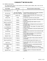
2. Simulate a Safety Shutoff Ignition Fail Test of the EOS control system:
−
With the manual gas valve at the burner closed, turn on the electrical service to the water heater, and then
turn the Conquest power switch to the ON position.
−
The EOS Temperature control touch screen will energize. If the tank temperature is 5 degrees or more
below the factory setpoint of 120 degrees, the Call-For-Heat sequence will initiate.
−
With no gas pressure, the ignition control will attempt to ignite the burner three times before proceeding to a
safety shutoff. Following the third failed attempt, the display screen immediately shows a
LOCKOUT
condition has occurred.
−
In a few seconds an
ERROR
code flashes in the Status field, and a
FLAME FAIL
alarm message is
displayed followed by the troubleshooting message
“IGNITION TRIAL FAIL”
which scrolls across the top of
the screen.
IMPORTANT:
Before restarting the unit, ensure there is a way for the system to dissipate heat. This can be
accomplished by opening one or more nearby hot water faucets.


