Nixie Tube Clock ‘Dink’
Issue 9 (10 November 2017)
www.pvelectronics.co.uk
- 11 -
4.3
4.2 Testing Low Voltage Power Components.
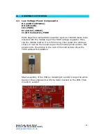
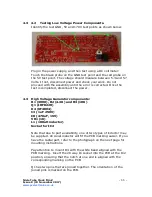
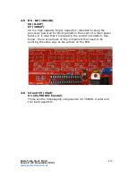
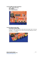
Identify the test GND, 5V and 170V test points as shown below.
Plug in the power supply, and then test using a DC voltmeter:
Touch the black probe on the GND test point and the red probe on
the 5V test point. The voltage should measure between 5.3 and 5.7
Volts. If not, disconnect power and check your work. Do not
proceed with the assembly until the error is corrected. Once the
test is completed, disconnect the power.
4.3
High Voltage Generator components:
R1 (390K), R2 (4.3K) and R3 (10K)
Q1 (IRFD220)
D4 (UF4004)
C3 (1uF 250V)
C8 (470uF, 16V)
VR1 (1K)
L1 (100uH inductor)
Socket for IC2
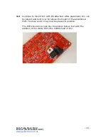
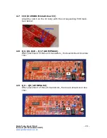
Note that due to part availability, one of two types of inductor may
be supplied. An Axial inductor will fit the PCB marking easier. If you
have the radial part, refer to the photograph on the next page for
mounting instructions.
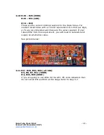
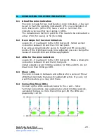
Pay attention to mount D4 with the white band aligned with the
PCB marking. Insert the 28 way IC socket into the PCB at the IC2
position, ensuring that the notch at one end is aligned with the
corresponding marking on the PCB.
Q1 has two pins that are joined together. The orientation of the
joined pins is marked on the PCB.


