Nixie Tube Clock ‘Dink’
Issue 9 (10 November 2017)
www.pvelectronics.co.uk
- 20 -
6.
CONNECTING THE OTHER INDICATORS
6.1 About the colon indicators
Provision is made for two multifunction colon indicators – they can
be set to flash the seconds, indicate AM /PM, or a combination of
both. Each colon (AM or PM) has a + and a – terminal. The
indicators can be either neon lamps or LEDs.
The indicators are fed from point J8. This needs to be connected to
either 170V (for neons) or 5V (for LEDs)
6.2 Neon lamps for the colon indicators
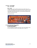
Locate J8 – it is adjacent to the 170V test point. Solder a small
connection between J8 and the 170V test point.
Now wire up small indicator neons to the AM and PM connection
points. If the brightness needs to be adjusted, you can change the
values of resistors R34 and R35 as appropriate
6.2 LEDs for the colon indicators
Locate J8 – it is adjacent to the 170V test point. Make a small wire
connection between J8 and the 5V test point.
Install suitable current limiting resistors for R34 and R35. Do not
draw more than 30mA per LED.
6.3 Show LEDs
Provision is made in hardware and software for a series of ‘Show’
LEDs that illuminate the tubes for added attraction. If you do not
want this feature, you may omit these.
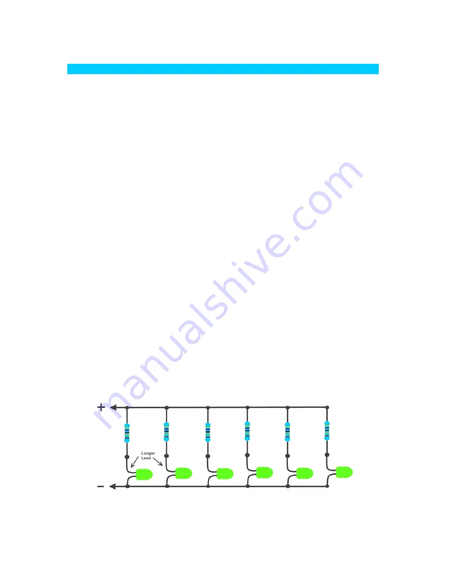
6.4 Connecting Show LEDs
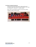
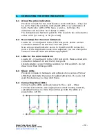
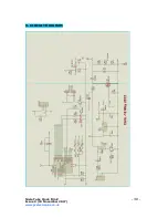
Connect up the LEDs as shown below to the + and – Show
Terminal Connections. Use appropriate current limiting resistors,
calculated to draw no more than 20mA per LED.The LEDs are
powered by 12V DC.

