UC10.241, UC10.242
UC-Series
24V,
15A,
CAPACITOR-BASED
DC-UPS
23.8.
E
XTERNAL
C
ONTROLLED
D
ELAYED
S
HUT
-
DOWN
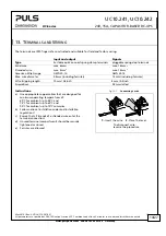
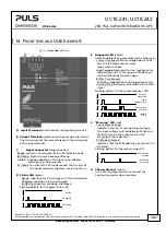
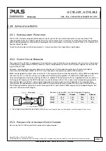
If the reset is supposed to be controlled by the PC or another external trigger and not the DC-UPS, the following
wiring option is possible but requires an external relay:
Fig. 23-6
Wiring scheme for an external controlled reset after a buffer event
25/27
+ +
- -
Power
Supply
24V Output
UC10
DC-UPS
IN
OUT
+
+
-
-
Inhibit
+
-
R
ead
y
B
u
fferin
g
P
C
M
ode
Relay
with NC
contact
Power Supply Output
DC-UPS Output
5s
70s
PC-Mode
Pin 7 & 8
connected
unit is in "waiting mode" for
a trigger on the inhibit input
Inhibit Input
>250ms
Ready
Contact
closed
External signal to start
the delayed shut-down
Load
+
-
open
closed
Buffering
Contact
open
<1s
full
empty
Capacitor
Pin 7 & 8
open
Ready Threshold
250ms
Activation of the “external control mode”:
The PC-Mode pins need to be connected together during a normal mode operation. This connection must be opened
within the first second of a buffer event to set the DC-UPS into the “external control mode”. In this mode, a signal on
the inhibit input will not immediately execute a shut-down of the DC-UPS’s output but will be delayed by 70s. The
output of the DC-UPS will always be switched off for at least 5s.
May 2016 / Rev. 2.2 DS-UC10.241-EN
All parameters are specified at 24V, 10A output current, 25°C ambient and after a 5 minutes run-in time unless otherwise noted.
www.pulspower.com Phone +49 89 9278 0 Germany

