


5099N Series User Manual
88
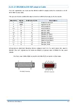
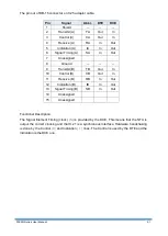
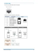
6.3 V.35 DB25(M) to M.34(F) adaptor Cable
If the DTE (Data Terminal Equipment) connector is using 34-pin Winchester type, we must use
the cable adaptor from DB-25 to Winchester (M.34).
The pin out of cable on DB-25(male) Connector to M.34(female) Connector:
DB-25 Pin
Signal
M.34 Pin
Description
2
TD
P
Transmit Data
14
TD
S
Transmit Data
3
RD
R
Receive Data
16
RD
T
Receive Data
4
RTS
C
Ready To Send
5
CTS
D
Clear To Send
6
DSR
E
Data Set Ready
20
DTR
H
Data Terminal Ready
24
XTC
U
DTE Transmit Clock
11
XTC
W
DTE Transmit Clock
15
TC
Y
Transmit Clock
12
TC
AA
Transmit Clock
17
RC
V
Receive Clock
9
RC
X
Receive Clock
1
FGND
A
Protective Ground
7
GND
B
Signal Ground
8
DCD
F
Data Carrier Detect
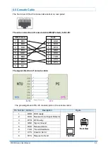
The front view of DB-25(M) connector and V.35(F) connector on this cable:
V.35 is a partially balanced, partially single-ended interface specification. The data leads and
clock leads are balanced; the handshake leads are single-ended.
TD, RD, TC, RC and XTC are differential signals conforming to RS-422/V.11. Remaining
control and handshake signals (RTS, CTS, DSR and DTR) are conformed to RS-232 as
unbalanced.
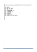
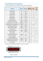
Summary of Contents for 5099N Series
Page 1: ...5099N Series G SHDSL bis NTU User Manual V1 00 ...
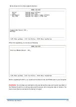
Page 18: ...5099N Series User Manual 15 For more detail on these sub menus please refer to following ...
Page 21: ...5099N Series User Manual 18 3 4 1 Show Statistic on E1 Interface ...
Page 33: ...5099N Series User Manual 30 ...
Page 34: ...5099N Series User Manual 31 ...
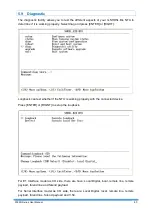
Page 43: ...5099N Series User Manual 40 5 4 1 Configure NTU Interface Setup Interface ...
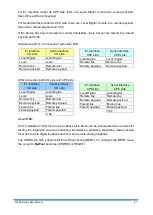
Page 78: ...5099N Series User Manual 75 For Serial interface mode ...
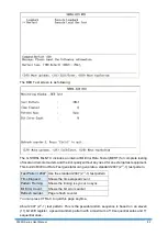
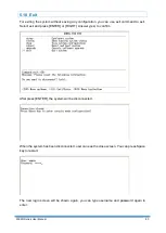
Page 81: ...5099N Series User Manual 78 When it is upgrading you can see the following ...


