


5099N Series User Manual
87
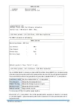
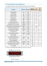
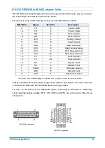
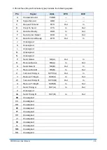
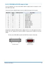
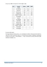
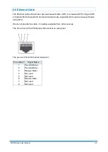
6.2 Serial Interface Pin Assignments
The table below displays Serial Interface Pin Assignments for the DCE Mode
.Function
Abbrev. Direction
RS-530
DB-25(F)
V.35
M.34(F)
X.21
DB-
15(F)
Frame Ground
FG
N/A
1
A
1
Transmit Data
TD
Input
2
P
2
Receive Data
RD
Output
3
R
4
Request to Send
RTS
Input
4
C
3
Clear to Send
CTS
Output
5
D
Data Set Ready
DSR
Output
6
E
Signal Ground
SG
N/A
7
B
8
Data Carrier Detect
DCD
Output
8
F
5
Secondary Receiver Clock
(S)RC
Output
9
X
13
Secondary Data Carrier Detect
(S)DCD
Output
10
12
Secondary External Transmitter Clock
(S)ETC
Input
11
W
7
Secondary Transmitter Clock
(S)TC
Output
12
AA
Secondary Clear to Send
(S)CTS
Output
13
Secondary Transmit Data
(S)TD
Input
14
S
9
Transmitter Clock
TC
Output
15
Y
Secondary Receive Data
(S)RD
Output
16
T
11
Receiver Clock
RC
Output
17
V
6
Local Loopback
18
Secondary Request to Send
(S)RTS
Input
19
10
Data Terminal Ready
DTR
Input
20
H
Remote Loopback
21
Secondary Data Set Ready
(S)DSR
Output
22
Secondary Data Terminal Ready
(S)DTR
Input
23
External Transmitter Clock
ETC
Input
24
U
14
Test Indicator
25
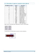
The front view of DB-25(F) Serial interface connector on rear panel:
Summary of Contents for 5099N Series
Page 1: ...5099N Series G SHDSL bis NTU User Manual V1 00 ...
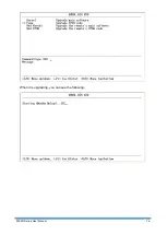
Page 18: ...5099N Series User Manual 15 For more detail on these sub menus please refer to following ...
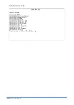
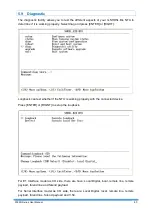
Page 21: ...5099N Series User Manual 18 3 4 1 Show Statistic on E1 Interface ...
Page 33: ...5099N Series User Manual 30 ...
Page 34: ...5099N Series User Manual 31 ...
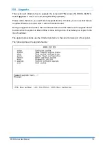
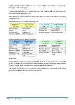
Page 43: ...5099N Series User Manual 40 5 4 1 Configure NTU Interface Setup Interface ...
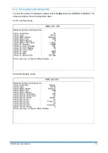
Page 78: ...5099N Series User Manual 75 For Serial interface mode ...
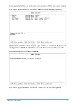
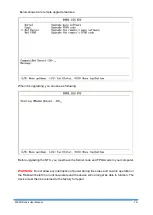
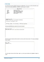
Page 81: ...5099N Series User Manual 78 When it is upgrading you can see the following ...


