


Pr
o
Minent
®
Page 8
Assembly and Installation
Installing pressure tubing
TAKE CARE
•
The discharge tubing should be laid in such a way as to ensure that the
pressure surge of the discharge stroke does not exceed the maximum
operating pressure. As overload protection for the discharge tubing, it is
advisable to fit a relief valve feeding back into the chemical supply container,
e.g. a ProMinent
®
multifunction valve.
•
Check that the length and cross section of the tubing are correct!
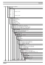
6.2.2
Installation of self-bleeding pumps
CAUTION
•
Observe all installation and safety guidelines for standard pumps!
•
Do not exceed tubing cross section, priming lift, priming pressure or
viscosity of feed chemical!
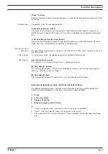
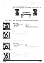
In addition to the suction and discharge tubing, a bypass tube should be connected. This is
attached to the bleed valve on the upper side of the liquid end (red packing, see fig. 06).
GUIDELINE
The discharge valve is located on the front of the liquid end in the SEK type!
Installation of by-pass tubing
GUIDELINE
When the suction side is primed, at least equal pressure must exist in the bypass
tubing!
The pump can operate when the bypass is primed and the suction side is
depressurised.
S
Place the tube onto the bypass nozzle and/or bleed valve of the self-bleed function liquid
end (recommended: flexible 6x4 PVC hose)
S
Push the free end of the tube back into the dosing container
S
Cut the bypass tube so that it does not enter the feed chemical.
Bleed valve for the bypass tube to the supply
container, 6/4 mm
Discharge valve for discharge tubing to injection
point, 6/4 - 12/9 mm
Suction valve for suction tubing in supply
container, 6/4 - 12/9 mm
Fig. 06